Creating a Floor plan, Footing detail and Isometric view using AutoCad
Figures drawn of challenge 2
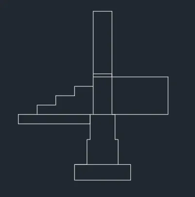
C1. Cross-section of load bearing wall over spread footing.
AIM – To draw cross section of load bearing wall over spread footing using AutoCAD software.
Procedure:
- Open AutoCAD
- Type QNEW in command box
- Click on imperial, quick set up, decimal
- Type units in command box
- Select decimal, precision set to 0.00, angle set to decimal degree.
- Type DS in the command box
- Snap spacing (x and y spacing)= 0.5
- Grid spacing (x and y spacing) = 0.1
- Major line set = 5
- Now for rectangle type REC in command box
- Specify the first corner point
- Click dimension in the command box
- Specify the length = 0.9 and width = 0.25 in the command box
- Type LINE in the command box.
- Specify the first corner point of second rectangle which 0.2 from the corner point of first rectangle.
- Type L in the command box and click on the last point which is 0.2 to specify corner point
- Type the L command and Give the length in upward direction as 0.4
- Type the L command and Give the length in right direction as 0.05.
- Type the L command and Give the length in upward direction as 0.4
- Type the L command and Give the length in right direction as 0.05.
- Now give the REC command and specify the first corner by clicking on the last point.
- Click on dimension in the command box and give the length as 0.6 and width as 0.3
- Type the REC command and specify the first corner point by clicking upper corner of last rectangle.
- Click on dimension box and Give the length as 0.3 and width as 0.05
- Type the REC command and specify the first corner point by clicking upper corner of last rectangle.
- Click on dimension box and Give the length as 0.3 and width as 1
- Type the REC Command and specify the first corner point by clicking on the lower right corner of rectangle (0.3x.05)
- Click on dimension box and Give the length as 0.9 and width as 0.6
- Type L in the command box and click on the lower right corner of rectangle (0.3x0.6).
- Give the length in right direction as 0.05
- Type the L command and give the length in downward direction as 0.4
- Type the L command and give the length in right direction as 0.05
- Type the L command and give the length in downward direction as 0.4
- Type REC command and specify the first corner point by clicking on the upper left corner of square (0.4x0.4).
- Click on the dimension in command box and give the length as 1.15 and width as 0.15
- Type the L command and specify the first point by clicking on the upper left corner of last rectangle(1.15x0.15)
- Give the length in right direction as 0.3.
- Type L command and give the length as 0.15 in upward direction.
- Repeat till 3 steps are created.
Result :
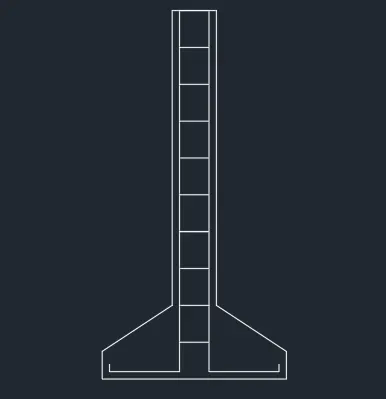
C2. Cross section of an isolated footing.
AIM – To draw cross section of an isolated footing using AutoCAD software.
Procedure:
- Open AutoCAD
- Type QNEW in command box
- Click on imperial, quick set up, decimal
- Type units in command box
- Select decimal, precision set to 0.00, angle set to decimal degree.
- Type DS in the command box
- Snap spacing (x and y spacing)= 0.5
- Grid spacing (x and y spacing) = 0.1
- Major line set = 5
- Type the L command give the length = 1unit
- Type L command and give the relative coordinate as @0,0.15
- Give the next coordinate as @0.38,0.25
- Next coordinate @0,1.6
- Next coordinate @0.24,0
- Next coordinate @0,-1.6
- Next coordinate @0.38,-.25
- Next coordinate @0,-.15 or close
- Now draw a line at a distance of 0.04 units from the top with line command
- Give the value 0.04 and then give length of 1st line 1.96
- Next coordinate @-0.38, 0 for the second line.
- Draw the third line, bend by giving the coordinate @0,0.04
- Copy the first line by command “co”, click displacement and give value 0.16 units.
- Copy the 2nd horizontal line by “co” specify base point and drag to the desired position
- Copy the 3rd line by giving command “co” and select the base point and drag it.
- Give offset from top line with an offset distance of 0.2 units
- Give command “o” and select the object giving the offset distance as 0.2 and select multiple options of 9 such lines.
- Trim the excess lines.
Result :
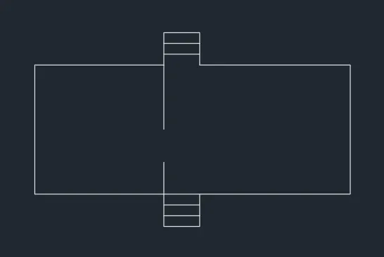
C3. Line diagram of a two bedroom building.
AIM - To draw the line diagram of two bedroom building using AutoCAD software.
Procedure:
- Open AutoCAD
- Type QNEW in command box
- Click on imperial, quick set up, decimal
- Type units in command box
- Select decimal, precision set to 0.00, angle set to decimal degree.
- Type DS in the command box
- Snap spacing (x and y spacing)= 0.5
- Grid spacing (x and y spacing) = 0.1
- Major line set = 5
- Select the command (pl) Polyline to create the bedroom of the given dimension
- Type the “pl” command and click the point and move the cursor to the left -x axis giving length as 3.6
- Move the cursor to up +y axis giving the length as 3.6
- Move the cursor to right +x axis giving the length as 3.6
- Move the cursor to down –y axis giving the length as 1.8
- Now use the line command for step outline.
- Now from the corner point of 1.8 give the length of 0.9 in +y axis.
- Move the cursor to right +x axis giving the length as 1 unit.
- Now give the length 0.9 unit in down in –y axis.
- Now again type the pl command from the last point for living room
- Type 4.2 units in +x axis direction
- Type 3.6 units in –y axis direction
- Type 4.2 units in –x axis direction
- Now type command “l” for the step
- Click the last point and move cursor in –y axis direction. Type 0.9 units
- Move cursor in –x axis direction and give the length as 1 unit
- Move the cursor in +y direction and give 0.9 units.
- Full Outline has been created.
- Now for steps use the offset command by typing “o” in command box.
- Give the offset distance as 0.3 unit and select the object
- Click on the multiple and move the cursor in upward direction and click where the steps are to be drawn.
- Do same for the other side.
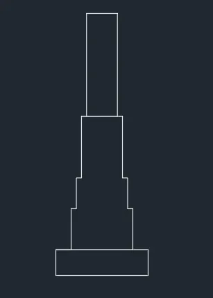
C4. Cross-section of load bearing wall showing foundation details.
AIM – To draw cross section of load bearing wall showing foundation details using AutoCAD software.
Procedure:
- Open AutoCAD
- Type QNEW in command box
- Click on imperial, quick set up, decimal
- Type units in command box
- Select decimal, precision set to 0.00, angle set to decimal degree.
- Type DS in the command box
- Snap spacing (x and y spacing)= 0.5
- Grid spacing (x and y spacing) = 0.1
- Major line set = 5
- Now for rectangle type REC in command box.
- Specify the starting point and click on dimensions giving the length as 0.9 units and width as 0.45 units.
- Select the polyline using the command “pl” and specify the first point 0.15 from the corner of rectangle.
- With the cursor pointing in +y direction give the distance as 0.4 units.
- With the cursor pointing in +x direction give the distance as 0.05 units.
- With the cursor pointing in +y direction give the distance as 0.3 units.
- With the cursor pointing in +x direction give the distance as 0.05 units.
- With the cursor pointing in +y direction give the distance as 0.6 units.
- With the cursor pointing in +x direction give the distance as 0.4 units.
- With the cursor pointing in -y direction give the distance as 0.6 units.
- With the cursor pointing in +x direction give the distance as 0.05 units.
- With the cursor pointing in -y direction give the distance as 0.3 units.
- With the cursor pointing in +x direction give the distance as 0.05 units.
- With the cursor pointing in -y direction give the distance as 0.4 units.
- The top potion is drawn using polyline
- Command “pl” then select the first at a distance of 0.05 from the corner point of top upper part.
- With the cursor pointing in +y direction give the distance as 1 units.
- With the cursor pointing in +x direction give the distance as 0.4 units.
- With the cursor pointing in +y direction give the distance as 1 units.
Result:
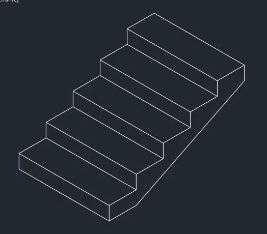
C5. Isometric view of steps.
AIM – To draw isometric view of steps using AutoCAD software.
Procedure:
- Open AutoCAD
- Type QNEW in command box
- Click on imperial, quick set up, decimal
- Type units in command box
- Select decimal, precision set to 0.00, angle set to decimal degree.
- Type DS in the command box
- Snap spacing (x and y spacing)= 0.5
- Grid spacing (x and y spacing) = 0.1
- Major line set = 5
- Activate the isometric view from the toggle bar then do the snap off, grid off and make sure that ortho mode is on
- From the isometric drafting select isoplane left
- Give the command “l” and move the cursor to –x direction and give 1 units
- Moving the cursor to +y direction and give 0.15 units.
- Moving the cursor to +x direction and give one unit, again move cursor to –y direction give -0.15 unit.
- Change the isometric view to isoplane top
- Move the cursor to back and give 0.3 units from the last drawn point
- Move the cursor to right direction and give one unit
- Move the cursor to the front and give 0.1 unit
- Change the isometric plane to isometric right
- Copy the object with ortho off
- Command “co” and specify the base point and place it to new point and repeat for 4 steps
- With the isoplane right draw the horizontal distance of 0.3 units from the starting point of stairs
- Draw a vertical distance of 0.15 units from the last stair.
- Join the two points with ortho off and the stair is drawn.
Result:
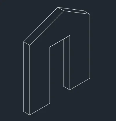
C6. Isometric view of Gable wall.
AIM – To draw isometric view of Gable wall using AutoCAD software.
Procedure:
- Open AutoCAD
- Type QNEW in command box
- Click on imperial, quick set up, decimal
- Type units in command box
- Select decimal, precision set to 0.00, angle set to decimal degree.
- Type DS in the command box
- Snap spacing (x and y spacing)= 0.5
- Grid spacing (x and y spacing) = 0.1
- Major line set = 5
- Activate the isometric view from the toggle bar then do the snap off, grid off and make sure that ortho mode is on
- From the isometric drafting select isoplane right.
- Type command “l” and draw the line of 1 unit by moving the cursor in left direction.
- Now draw the line 3 unit in +y axis direction.
- Now change the plane to isometric left
- Now draw the line 0.3 unit by moving cursor in left.
- Now draw the line of 3 unit in –y direction and 0.3 unit line in right direction. Now the rectangle of 0.3x3 is seen.
- Now click on the very first point from where we started and draw the line of 2.4 units
- Change the plane to isometric right
- Draw the line of 1 unit by moving cursor right
- Draw the line of 2.4 unit again downwards.
- Change the plane to isometric left
- Draw a line of 0.3 unit in –x direction (as seen in isoplane view)
- Draw a line of 2.12 units in upward direction.
- Now again from last point draw a line of 1.43 units upwards.
- Now draw the line of 0.3 in –x direction (isometric view)
- Now type command “l” click on the opposite point of starting point of the entry gate.
- Draw the 1 unit in + direction.
- Now draw the line in upward direction of 3 units.
- Now draw the line of 0.3 unit in –x direction. (isometric view)
- Now join all the lines diagonally by keeping ortho off
- Now use “trim” command and trim the 1.43 unit line.
- Gable wall is drawn.
Result: