Drafting of various geometries using Chamfer, Fillet tool in AutoCad
Aim:
To create various geometries using “Chamfer” and “Fillet” tool in AutoCAD
Default settings.
- Open AutoCAD
- Open new drawing
- Set units (measurements as engineering , angle as decimal degree)
- Enable Ortho mode on
Object snap settings
- Type “OS” in command box
- In drafting settings box open object snap and switch on all the necessary options
- Click ok
Problem 1
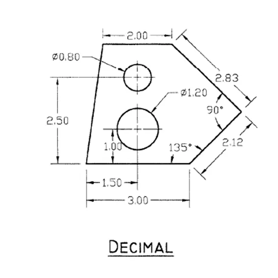
Procedure:
Step 1
- Set unit to decimal and precision to 0.0
- Start with line tool by entering “L” in command box
- Specify the first point 1,1
- Next point @3,0
- Next point @2.12<45
- Next point @2.08<135
- Next point @-2,0
- Then enter close to complete the box
Step 2
- Use offset tool
- Type “off” in command box
- Give a distance of 1 unit
- Using cursor Click on bottom line and move the cursor top and click enter
- Repeat the same step with a distance of 2.5 units also
- Select line tool
- From the centre of bottom line start a line and move to top like it bisects the two offset lines
Step 3
- Select circle tool (centre and radius)
- Using cursor click at the first intersection and give a radius of 0.6
- Using cursor click at the second intersection and give a radius of 0.4
Step 4
- Finally delete the unwanted lines
- Give dimensions by using dimension tool from tool box
Result
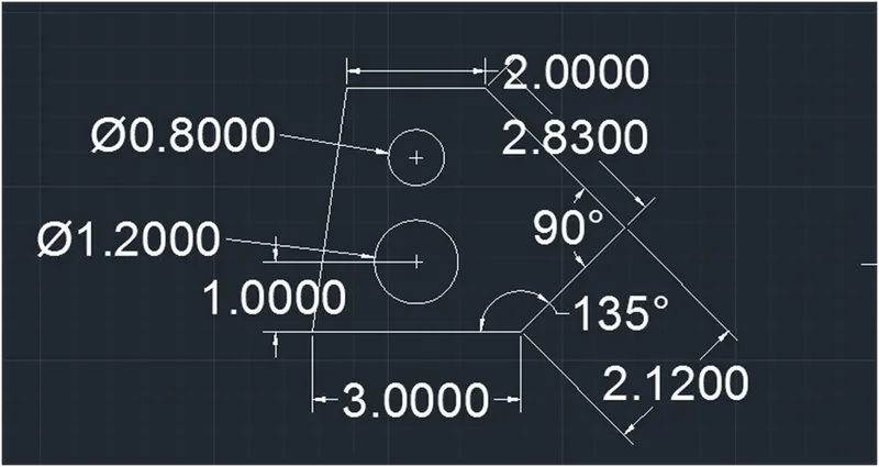
Problem 2
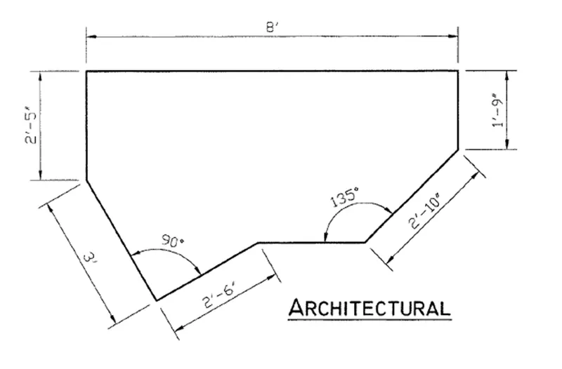
Procedure:
Step 1
- Set unit to engineering and precision to 0’-0.0”
- Enter command dimstyle and click on modify
- Set unit to engineering and precision to 0’-0.0”
Step 2
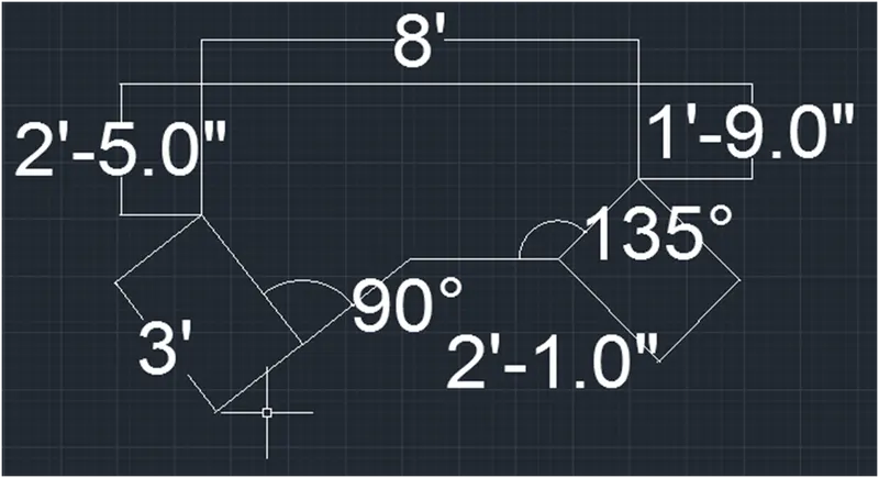
- Select line tool and specify the first point at 1,1
- Specify the next point 8’ by moving cursor right side
- Specify the next point 1’-9” by moving cursor downward
- Specify the next point @2’-10”<-135
- Press enter
Step 3
- Select line tool and specify the first point at 1,1
- Specify the next point 2’-5” by moving cursor downward
- Specify the next point @3’<-60
- Specify the next point @2’-6”<30
- Then join the two ends and press enter
- By using dimension tool give all necessary dimensions
Result
Problem 3
Procedure:
Step 1
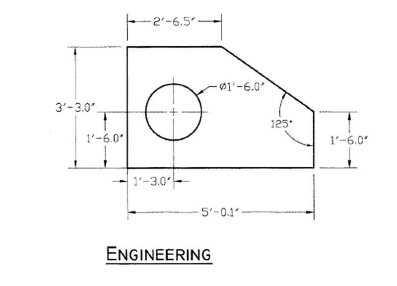
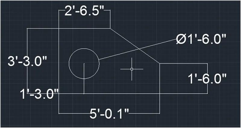
- Select line tool and specify the first point at 5,5
- Specify the next point 2’-6.5” by moving cursor left side
- Specify the next point 3’-3” by moving cursor downwards
- Specify the next point 5’-0.1” by moving cursor right side
- Specify the next point 1’-6” by moving cursor upwards
- Then enter close to complete the circuit
Step 2
- Use offset tool
- Type “off” in command box
- Give a distance of 1’6”
- Using cursor Click on bottom line and move the cursor top and click enter
- Type “off” in command box
- Give a distance of 1’3”
- Using cursor Click on left most line and move the cursor right side and click enter
Step 3
- Select circle tool (centre and dia)
- Using cursor click at the first intersection and give a dia of 1’-6”
- Finally delete the unwanted lines
- Give dimensions by using dimension tool from tool box
Result
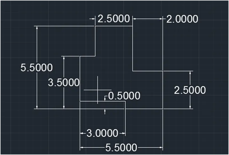
Problem 4
Procedure:
Step 1
- Set unit to decimal and precision to 0.0
- Select line tool by using “L” in command box
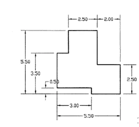
- Select line tool and specify the first point at 1,1
- Specify the next point 0.5 by moving the cursor upward
- Specify the next point 3 by moving the cursor leftside
- Specify the next point 3 by moving the cursor upward
- Specify the next point 1 by moving the cursor right side
- Specify the next point 2 by moving the cursor upward
- Specify the next point 2.5 by moving the cursor right side
- Specify the next point 3 by moving the cursor downwards
- Specify the next point 2 by moving the cursor right side
- Specify the next point 2.5 by moving the cursor downwards
- Specify the next point 2.5 by moving the cursor left side
- Press enter to close the circuit
- Give dimensions by using dimension tool from tool box
Result
Problem 5
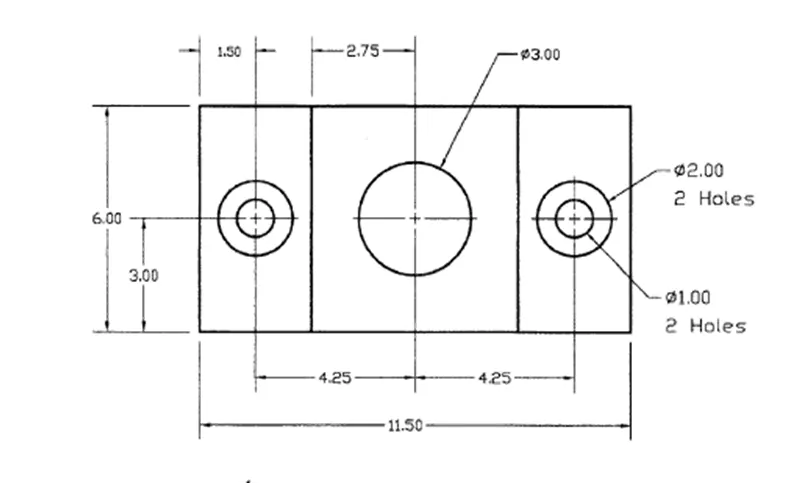
Procedure:
Step 1
- Select line tool by using “L” in command box
- Select line tool and specify the first point at 1,1
- Specify the next point @11.5,0
- Specify the next point @0,6
- Specify the next point @-11.5,0
- Enter close to complete the circuit
Step 2
- Use offset tool
- Type “off” in command box
- Give a distance of 3 unit
- Using cursor Click on leftmost line and move the cursor right and click enter
- Using cursor Click on rightmost line and move the cursor left and click enter
Step 3
- Use offset tool
- Type “off” in command box
- Give a distance of 1.5 unit
- Using cursor Click on leftmost line and move the cursor right and click enter
- Using cursor Click on rightmost line and move the cursor left and click enter
- Type “off” in command box
- Give a distance of 3 unit
- Using cursor Click on bottom line and move the cursor up and click enter
- Select line tool
- Start the line from midpoint of bottom line and end at mid point of top line
Step 4
- Select circle tool (centre and radius)
- Using cursor click at the first intersection and give a radius of 0.5
- Using cursor click at the first intersection and give a radius of 1
- Repeat the same for final intersection also
- Select circle tool (centre and radius)
- Using cursor click at the mid intersection and give a radius of 1.5
- Click enter
Step 5
- Finally delete the unwanted lines
- Give dimensions by using dimension tool from tool box
Result
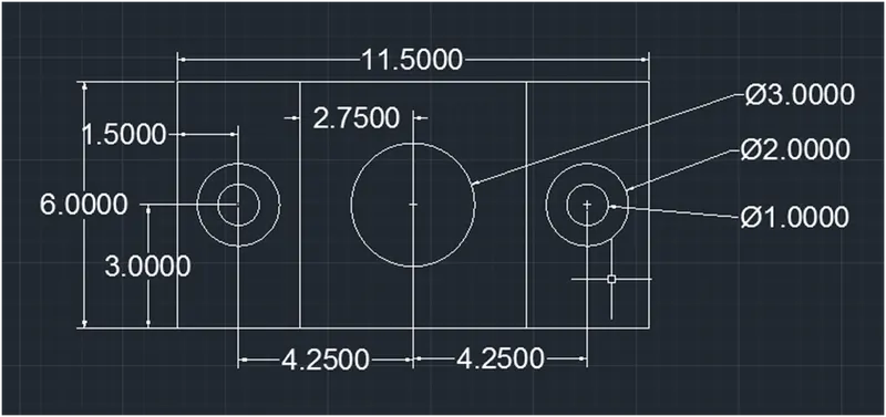
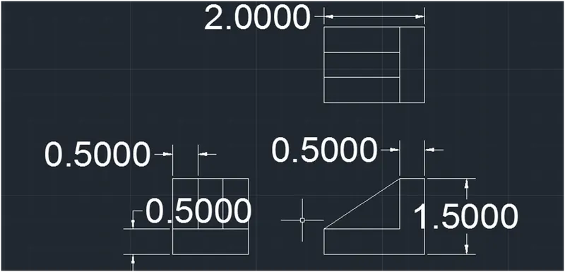
Problem 6
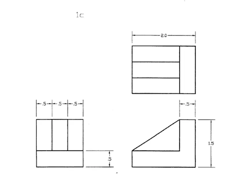
Procedure:
Step 1
- Select x-line tool by using “xl” in command box
- Select horizontal and click on screen to draw horizontal line
- Select vertical and click on screen to draw vertical line
Step 2
- Use offset tool
- Type “off” in command box
- Give a distance of 0.5 unit
- Using cursor Click on vertical line and move the cursor left and click enter
- Using cursor Click on horizontal line and move the cursor up and click enter
- Type “off” in command box
- Give a distance of 2 unit
- Using cursor Click on vertical line and move the cursor left and click enter
- Type “off” in command box
- Give a distance of 1.5 unit
- Using cursor Click on horizontal line and move the cursor up and click enter
- Type “off” in command box
- Give a distance of 3 unit
- Using cursor Click on horizontal line and move the cursor up and click enter
- Using cursor Click on vertical line and move the cursor left and click enter
Step 4
- Now using trim tool delete the all unwanted lines
Step 5
- Type “off” in command box
- Give a distance of 0.5 unit
- Now draw lines for top and left rectangles as shown
- Press esc
- Now trim the top lines of the middle rectangle
- Using line tool draw a line connecting the two corners
- Give dimensions by using dimension tool from tool box
Result
Problem 7
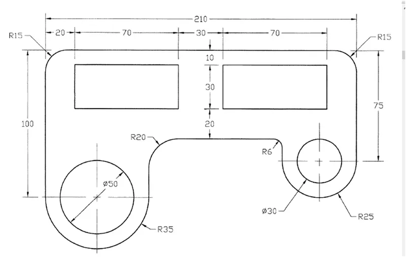
Procedure:
Step 1
- Select line tool by using “L” in command box
- Select line tool and specify the first point at 30,30
- Specify the next point @0,100
- Specify the next point @210,0
- Specify the next point @0,-75
- Press esc
Step 2
- Use offset tool
- Type “off” in command box
- Give a distance of 10 unit
- Using cursor Click on top line and move the cursor down and click enter
- Give a distance of 30 unit
- Using cursor Click on offset line and move the cursor down and click enter
- Give a distance of 20 unit
- Using cursor Click on offset line and move the cursor down and click enter
- Using cursor Click on left line and move the cursor rightside and click enter
- Using cursor Click on right line and move the cursor leftside and click enter
- Give a distance of 70 unit
- Using cursor Click on left line and move the cursor rightside and click enter
- Using cursor Click on right line and move the cursor leftside and click enter
- Now using trim command delete the unwanted lines
Step 3
- Now select point tool and place a point 25 units left from the bottom of rightmost line
- place a point 35 units right from the bottom of lefttmost line
Step 4
- Select circle tool (centre and radius)
- Using cursor click at the right point and give a radius of 35
- Using cursor click at the right point and give a radius of 25
- Using cursor click at the left point and give a radius of 25
- Using cursor click at the left point and give a radius of 15
Step 5
- Use fillet tool
- Type “fillet” in command box
- Select angle and give a radius of 15
- Select topline and left line
- And Select topline and right line
- Type “fillet” in command box
- Select angle and give a radius of 20
- Select bottom line and outer circle
- Type “fillet” in command box
- Select angle and give a radius of 6
- Select bottom line and outer circle
- Press esc
- Give dimensions by using dimension tool from tool box
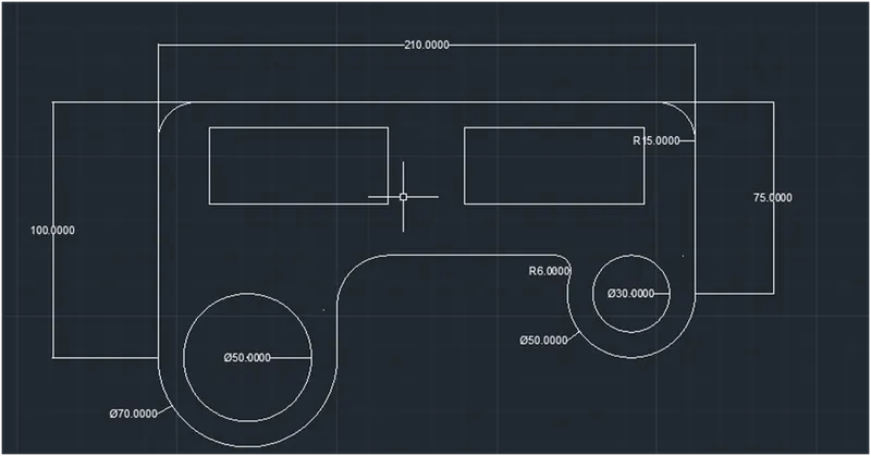
Result
Problem 8
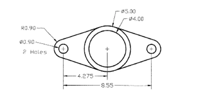
Procedure:
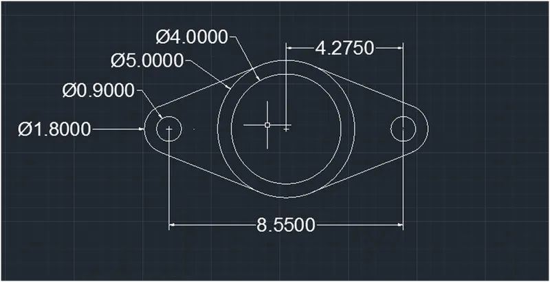
Step 1
- Select circle tool (centre and radius)
- Using cursor click at a point and give a radius of 2
- Using cursor click at the same point and give a radius of 2.5
Step 2
- Now select point tool and place a point 4.275 units left and right from the centre of the circle
Step 3
- Select circle tool (centre and radius)
- Using cursor click at the right point and give a radius of 0.45
- Using cursor click at the same right point and give a radius of 0.9
- Do the same procedure for left point also
Step 4
- Select line tool
- Press the right click of the mouse by holding shift key
- Select tangent option from the box
- Select the two circles and press enter
- Repeat the same procedure for all the tangents
Step 5
- Trim the unwanted lines
- Give dimensions by using dimension tool from tool box
Result
Problem 9
Procedure:
Step 1
- Set unit to engineering and precision to 0’-0.0”
- Enter command dimstyle and click on modify
- Set unit to engineering and precision to 0’-0.0”
Step 2
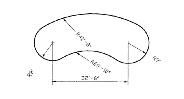
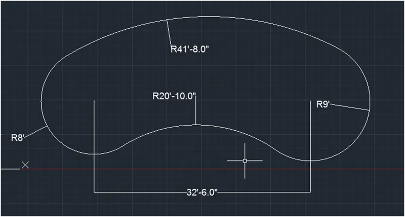
- Draw a circle 1 of radius 8’ from point 1,1
- Draw a circle 2 of radius 9’ from point 32’6” from the centre of c1
- Draw a circle of (tangent, tangent, radius) radius of 41’8” by selecting c1 and c2
- Draw a circle of (tangent, tangent, radius) radius of 20’10” by selecting c1 and c2
Step 3
- Trim the unwanted lines using trim tool
- Give dimensions by using dimension tool from tool box
Result
Problem 10
Procedure:
Step 1
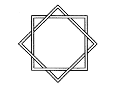
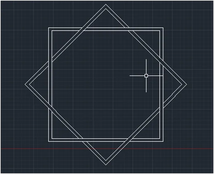
- Select rectangle tool from tool box
- Give dimension as 20’ and 20’
- Press enter
- Select offset tool
- Give a offset of 10”
- And make inside offset of rectangle
Step 2
- Now select copy tool
- Select the entire rectangle and make other copy
- Press enter
- Now select rotate tool
- Select the copied rectangle and rotate it 45 degree
- Now select move tool
- Select at mid point of rotated rectangle
- And move it to the centre of rectangle 1 using cursor
- Press enter
Step 3
- Select trim tool
- Trim the places as shown in the fig
Result
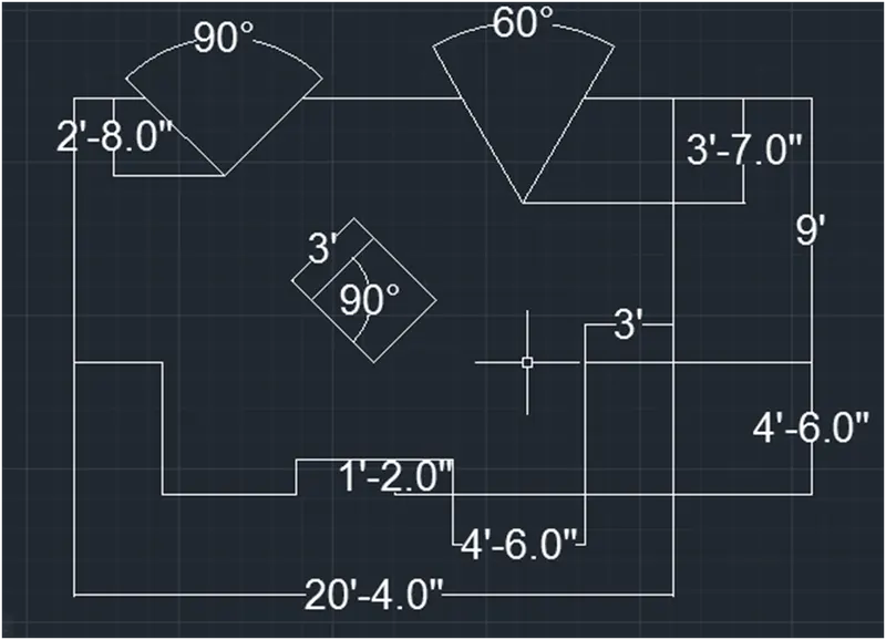
Problem 11
Procedure:
Step 1
- Set unit to engineering and precision to 0’-0.0”
- Enter command dimstyle and click on modify
- Set unit to engineering and precision to 0’-0.0”
Step 2
- Select rectangle tool
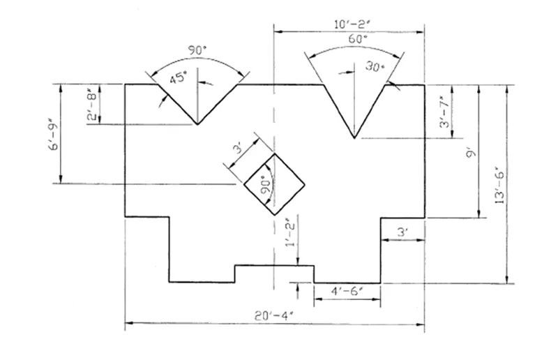
- Draw a rectangle of length 20’4” and width as 9’ from 1,1
- Select line tool
- Start point at 3’ from bottom left corner of rectangle
- Next point @0,4’6”
- Next point @4’6”,0
- Next point @0,-1’2”
- Next point @5’6”,0
- Next point @0,1’2”
- Next point @4’6”,0
- Next point @0,-4’6”
- Press enter
- Not trim the unwanted lines
Step 3
- Now select rectangle tool
- Use dimensions
- Give length and width as 3’
- Now select rotate tool
- Select the rectangle and rotate it 45 degree
- Now select move tool
- Select at mid point of rotated rectangle
- And move it to the 6’9” bottom to the cenere of main rectangle using cursor
Step 4
- Now draw a triangle of height 2’8” and angle of 90degree
- And draw a other rectangle of height 3’7” and angle of 60degree
- Use move tool to place the triangles at required places as shown in fig
- Now use trim tool to remove the lines at required places
- Give dimensions by using dimension tool from tool box
Result