Creating a Residence Layout, Seating plan, Toilet and Utility room plan using AutoCad
Problem 1
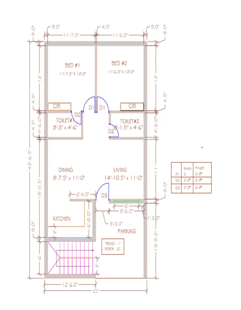
Aim: To Sketch the layout of a residence as shown in the Figure
Procedure:
Step 1 Basic settings
- Open AutoCAD
- Open new drawing
- Set units (measurements as engineering, precision to 0’-0.0” , angle as decimal degree)
- Enable Ortho mode on
Step 2
- Enter command dimstyle and click on modify
- Set unit to engineering and precision to 0’-0.0”
Step 3 WALLS
- Use X-line by typing “XL” in command box
- Select vertical and plot a line by using cursor
- Use X-line by typing “XL” in command box
- Select horizontal and plot a line by using cursor
Step 4
- Use offset tool by “off” in command box
- Give a length as 9”
- By using cursor click on the both x lines and plot offsets inside
- Use offset command
- Give a length as 6’
- By using cursor click on the horizontal x lines and plot offsets upward
- Use offset command
- Give a length as 9”
- By using cursor click on the horizontal x lines and plot offsets upward
- Use offset command
- Give a length as 6’8”
- By using cursor click on the horizontal x lines and plot offsets upward
- Use offset command
- Give a length as 4.5”
- By using cursor click on the horizontal x lines and plot offsets upward
- Use offset command
- Give a length as 11’
- By using cursor click on the horizontal x lines and plot offsets upward
- Use offset command
- Give a length as 4.5”
- By using cursor click on the horizontal x lines and plot offsets upward
- Use offset command
- Give a length as 4’6”
- By using cursor click on the horizontal x lines and plot offsets upward
- Use offset command
- Give a length as 4.5”
- By using cursor click on the horizontal x lines and plot offsets upward
- Use offset command
- Give a length as 12’
- By using cursor click on the horizontal x lines and plot offsets upward
- Use offset command
- Give a length as 9”
- By using cursor click on the horizontal x lines and plot offsets upward
Step 5
- By using “TRIM” command delete the all unwanted lines at joints
Step 6
- Use offset tool by “off” in command box
- Give a length as 11’7.5”
- By using cursor click on the vertical x lines at bed#1 and plot offsets right side
- Use offset command
- Give a length as 4.5”
- By using cursor click on the previous vertical x lines at bed#1 and plot offsets right side
- Use offset command
- Give a length as 11’6”
- By using cursor click on the previous vertical x lines at bed#2 and plot offsets right side
- Use offset command
- Give a length as 9”
- By using cursor click on the previous vertical x lines at bed#2 and plot offsets right side
Step7
- Use extend tool and extend the final 2 lines upto the bottom horizontal x-line
- Use offset tool by “off” in command box
- Give a length as 11’9”
- By using cursor click on the vertical x lines at parking and plot offsets left side
- Use offset command
- Give a length as 9”
- By using cursor click on the vertical x lines at kitchen and plot offsets left side
- Use “trim” command and delete all unwanted lines as per given figure
Step 8 DOORS
- Select rectangle
- Plot line at starting point outside the plan
- Give a length of 3’ and width of 1”
- And press enter
- Select line tool
- From the point 1” from the left bottom of rectangle
- Move the cursor up ward and give a length of 2’10” press ent
- Use curve tool and join the line top and rectangle bottom to produce curve
- Now use trim tool to delete the unwanted section
- Use join tool and select all the objects in the door to joint all as one
- Use copy tool to copy the door and use rotate to rotate the door as per the given fig
- Do the same procedure for D2 and D3 also
- Now use move tool
- Select the corner of door
- Stick at the required place as per drawing
- Use trim tool to trim the existing lines
Step 9 Kitchen Platform
- Use offset tool by “off” in command box
- Give a length as 2’
- Select the line in kitchen and move the cursor upward and press enter
- Do the same for vertical line also
- Now trim the unwanted portion
Step 10 Window
- Select line tool and draw at the joint between living and parking wall
- Move the line 1’3” from the joint using move tool
- Select offset tool and give a length of 6’
- Click on the line move the cursor left side and press enter
- Select line tool and draw a line by joining the centre of 2 lines
Step 11 cupboard
- Select rectangle tool
- Give length and width as 8’7.5” and 2’
- Press enter
- Select offset tool
- Give length as 2”
- Give inside offset for rectangle
- Now copy the rectangle using copy tool
- And place it bed room 1 & 2 as given
Step 12 staircase
- Select offset tool
- Give length as 3’
- Select the outline of kitchen wall
- Move the cursor downward and press enter
- Select offset tool
- Give length as 1”
- Select the previous offset line and give offset lies both sides by cursor
- Now delete the middle line
- Select line tool and draw the first line
- Now select copy tool
- Select the line
- Now select array tool in command box
- Give no of 10 and distance of 1’
- Press enter
- Now delete the first line
- Select trim tool
- And delete the unwanted lines
Step 13 Dimensions
- Select dimensions tool from ribbon
- And give the all dimensions as given in diagram
Step 14 text
- Select text tool by typing text in command box
- Click the cursor at required points
- Give the text as shown in figure
- Can change the height of text by right click on the text given and properties tab
Step 15 layers
- Go to layer properties from home ribbon
- Now select new layer
- Rename it as wall ext and assign colour
- Do the same for diff layers and assign diff colours
- Press enter and close
- Now select the lines and assign the layers from layer panel in home ribbon
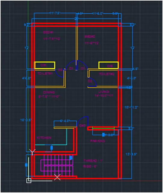
Result :
Problem 2
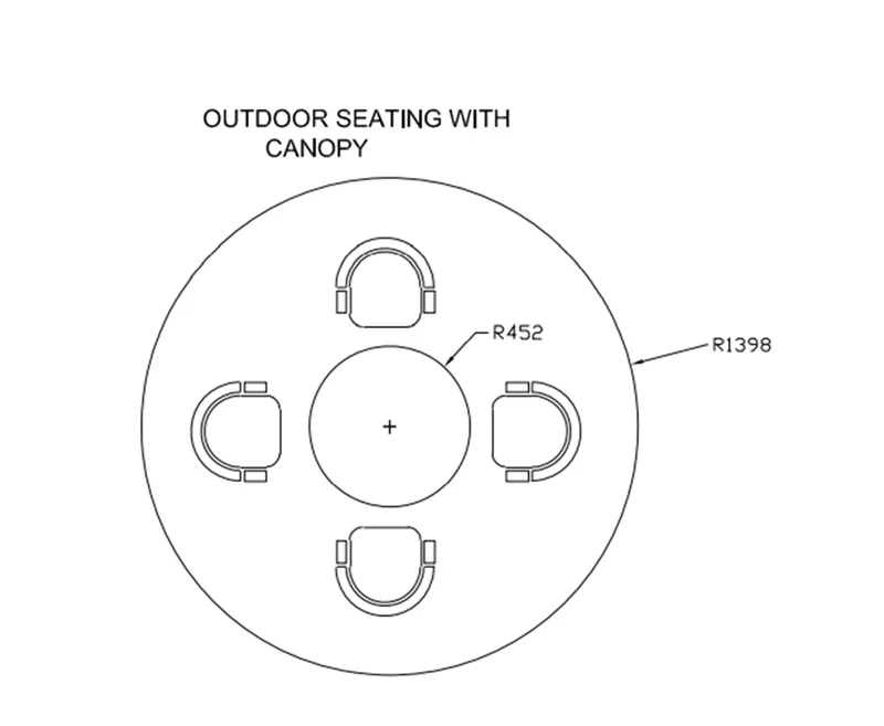
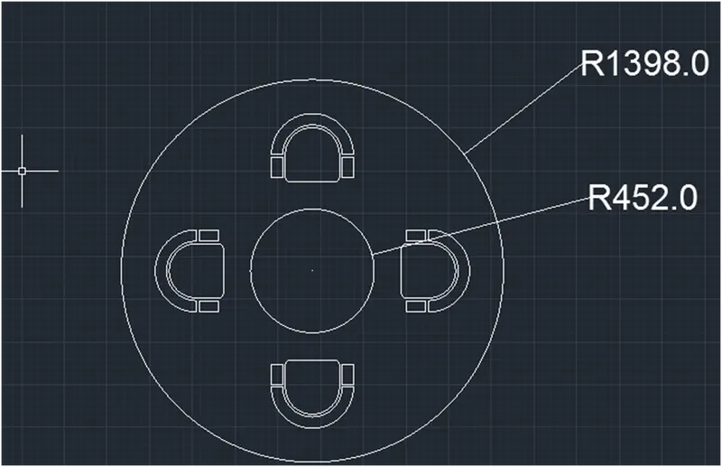
Aim: To Sketch the layout of a residence as shown in the Figure
Procedure:
Step 1 Basic settings
- Open AutoCAD
- Open new drawing
- Set units (measurements as decimal, precision to 0.0 and basic units as mm , angle as decimal degree)
- Enable Ortho mode on
Step 2
- Enter command dimstyle and click on modify
- Set unit to engineering and precision to 0.0
Step 3
- Draw a circle with command “C”
- Select a centre point and give a radius of 1398mm
- Draw a another circle with same centre and radius of 452mm
Step 4
- Select offset tool and give a length of 200
- Draw a offset for inner circle
- Select line tool
- Draw the lines along the X and Y axis of the dia of bigger circle
Step 5 Drawing chairs
- Draw a rectangle of length and width as 400,200
- Draw an arc along the top of the rectangle
- Give offsets of 50 mm for the arc and rectangle
- Give another offset of 100 mm for outer arc and rectandle
- Now trim the unwanted lines as given in fig
- Use fillet command and give an angle of 50 and apply it for inner rectangle
- Now select the entire chair and apply “join” tool
- Now use copy command and produce 4 copies
- Use rotate command and rotate the chairs to 90,180,270 degree each
- Now use move tool and move the chairs to the position using the mid point of the chair placing it to the joint of mid circle and line
Step 6
- Now delete the mid circle and lines
- Give the dimensions using “Dimangle” tool
Result:
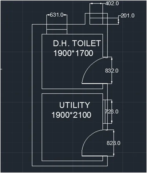
Problem 3
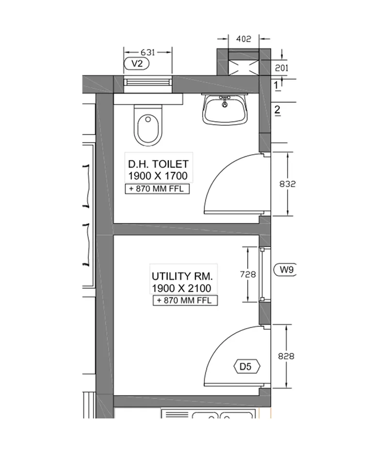
Aim: To Sketch the layout of a residence as shown in the Figure
Procedure:
Step 1 Basic settings
- Open AutoCAD
- Open new drawing
- Set units (measurements as decimal, precision to 0.0 and basic units as mm , angle as decimal degree)
- Enable Ortho mode on
Step 2
- Enter command dimstyle and click on modify
- Set unit to engineering and precision to 0.0
Step 3
- Draw construction lines by using “XL” in command box and selecting h and v
- Trim the left and bottom of lines using trim tool
Strp 4 utility
- Draw an offset of 300mm from the left side of vertical line and 15 mm from the horizontal line
- Draw an offset of 2100mm upwards and 1900 mm towards right side
- Give a wall thickness of 150mm and 30 mm using offset tool
Step 5 DH Toilet
- Draw offset of 1700mm upwards and wall thickness of 300 as it is the external wall and room is formed command “O”
- Now trim the unwanted lines by trim tool
Step 6 doors
- In utility offset a distance of 200mm from wall and give a offset of 828 mm
- Trim the opening by trim tool
- In utility offset a distance of 100mm from wall and give a offset of 832 mm
- Trim the opening by trim tool
- Draw the door swing by using line and arc tools
Step 7 window
- Draw a window of 728 mm in utility and a ventilator of 631 mm in toilet sing line tool
Step 8
- Draw a rectangle of length and width as 402 , 201
- Give offset of 150 for rectangle to outside
- Now trim the bottom line
- Move the rectangle to the corner of toilet to form a duct as shown in fig
Step 9 text
- Select text tool by typing text in command box
- Click the cursor at required points
- Give the text as shown in figure
- Can change the height of text by right click on the text given and properties tab
Step 10 Dimensions
- Select dimensions tool from ribbon
- And give the all dimensions as given in diagram
Result: