Drafting of various geometries using Chamfer, Fillet tool in AutoCad
Aim: To draw the given sketches in autocad.
Introduction: autocad offers various tools like rotate,chamfer,fillet,move,offset etc to ease thr sketching process.
Command used : Line, circle, chamfer, fillet, mirror, trim, move, rotate, annotate.
Procedure:
Drawing 1:
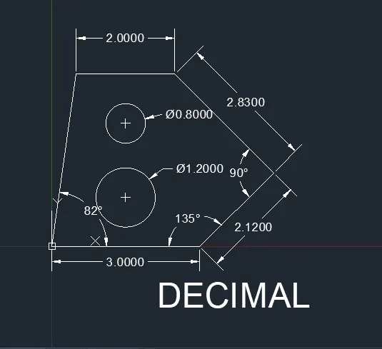
Procedure:
1.First in new drawing are setup in decimal units.
2.Using line command with the starting coordinates as 0,0 for the starting point.
3.Then for the next point use line command and coordinates as (@2.12<45Degrees),(@2.83<135D),(@2<180D) and enter c for close.
4.Then we got the required closed box.
5.For the circles inisde the box use circle command.
6.Enter the circle command use coordinates as (1.5,1.3) and click on diameter and enter the value D as 1.200.
7.For the next circle enter circle command use coordinates as (1.5,2.5) and click on diameter and enter the value of D as 0.8.
8.Then we got the drawing as per the specifications.
Drawing 2:
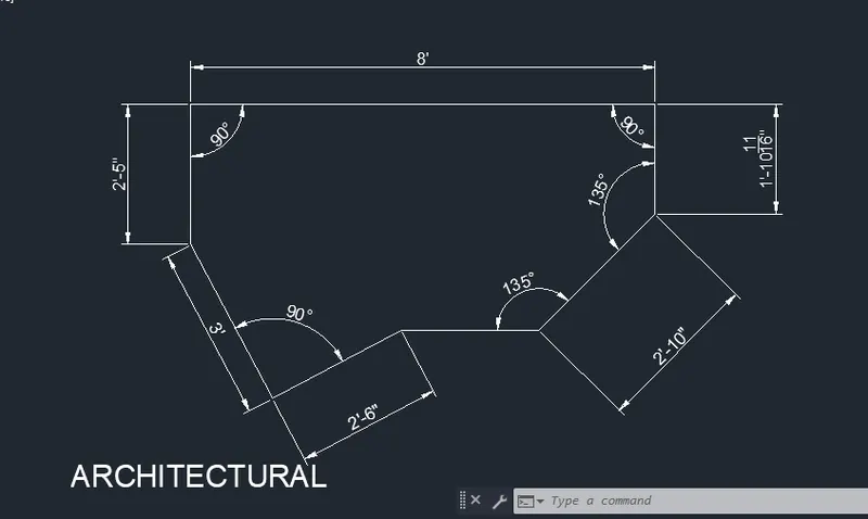
1.First we have to set units to architectural and start drawing.
2.Then with line command use coordinates 2'1",0 as the starting point.
3.Then next point as (@2'6"<45d) and from the same point (@3'<135d) from that point next point as follows.
4.(@2'5"<90d),(@8'<0d),(@1'9"<270d),(@2'10"<225d).
5.next join the lines of 2'10" line to 2'6" line as shown in figure.
6.Then we got the required drawing using architectural units.
DRAWING 3 :
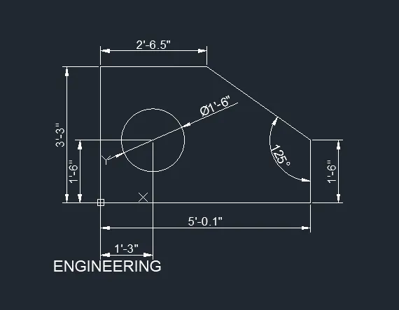
1.First using line command of coordinates 0,0 as the starting point.
2.Then the next point as (@5'.01"<0d),(@1'6"<90d) after we dont know the length.
3.Then go to starting point as 0,0 and next point as (@3'3"<90d),(@2'6.5"<0d).
4.Then from the point we have to close the box by joining the lines.
5.For the circle in the box we have to use circle command and coordinates as (1'3",1'6") and click on diameter and enter the value as 1'6" as diameter.
6.Then specify the dimensions and we got the drawing.
Drawing 4:
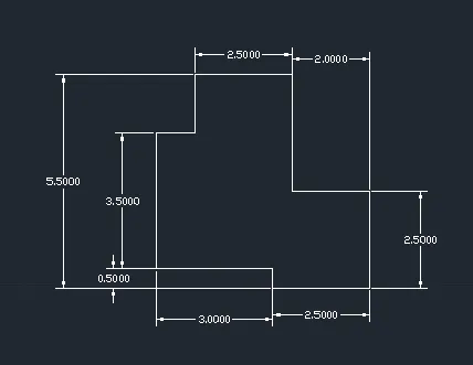
1.First we have click line command use starting point as 0,0.50.
2.The next points are (@3<0d),(@0.50<270d),(@2.5<0d),(@2.5<90d),(@2<180d),(@2.5<180d),(@1.5<270d),(@3.5<270d).
3.Then the given drawing is closed.
4.Then specify the dimensions of the given drawing.
Drawing 5:
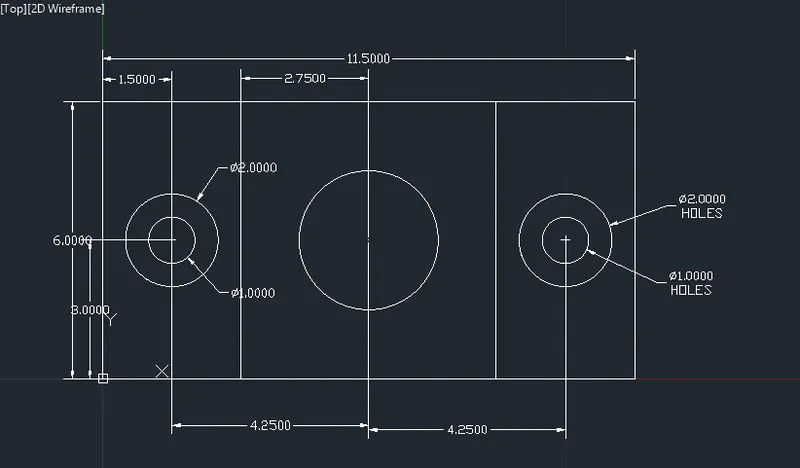
1.First use line command and coordinates as 0,0.
2.Then using line command the next point as (@6<90d),(@11.5<0d),(@6<270d) and enter c for close.
3.Then click on offset command and enter the offset distance as 3' and give the first line.
4.Then give the offset value as 5.5 and give the second line.
5.Then we got the three portions.
4.In the first portion we have to draw a circles of diameter as 1 and 2.
5.Click circle command and enter the coordinates as 1.5,3 and specify first diamter as 1 and with the same coordinates give the second dia as 2.
6.Then in the second portion enter circle command and enter coordinates as 5.75,3 and give the diameter as 3.
7.And in the third portion enter circle command and coordinates as 10,3 and enter diameters as 1and 2 with the same coordinates.
8.Then we got the required drawing.
DRAWING 6:
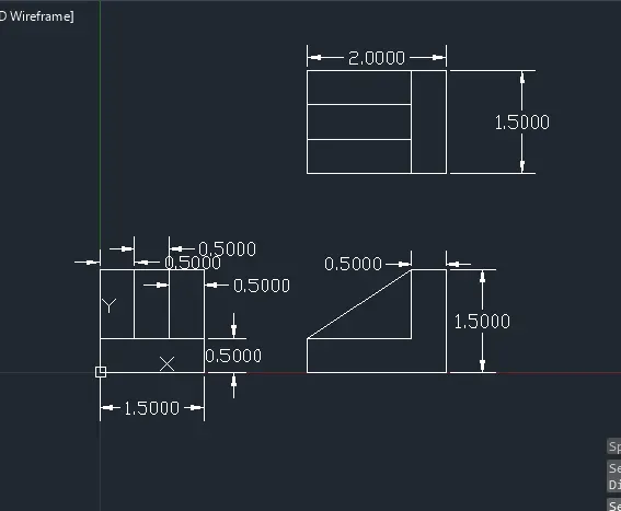
1.First from the 0,0 coordinate enter line command and enter (@1.5<0),(@1.5<90d),(@1.5<180d) and enter c for close.
2.click offset command and enter value as 0.5 and create offset in the middle.
3.Then in the section drawing in right side With line command (@2<0d),(@1.5<90d),(@0.5<180d),(@1<270d),(@1.5<180d) and enter c for close.
4.And draw slope from two points as shown in figure.
5.Then for the plan we use line command (@1.5<90d),(@2<0d),(@1.5<270d) and enter c for close.
6.then select offset command and enter the value of 0.5 and create the lines in vertical direction.
7. Then we specify the dimensions of the drawing.
DRAWING 7:
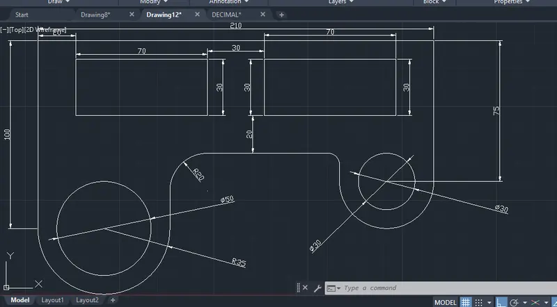
1.First use line command and enter at any point.
2.Next point is (@100<90d),(@210<0d),(@75<270d).
3.Then we have create circles at the bottom enter circle command and enter point at starting point and in x direction as 35 units as given in figure.
4. then enter the diameter and enter the value of 50 diameter. and from the same point enter the circle command and enter 35 radius.
5.Then for the right side of the drawing there are a circles a the bottom, so enter circle command and specify the point as shoun in figure.
6.Then enter the value of the circle as 30 diamter and at the same point enter circle command the radius as 25.
7.Then after enter the line command sepcify the point from left top as in x axis as 2 units.
8.Then we have to create the two rectangles use line command (@70<0d),(@30<270d),(@70<180d) then enter c for close the box.
9.Then from the first rectangle the second is from 30 units from the first.
10.Use line command and enter (@70<0d),(@30<270d),(@70<180d) and enter c for close.
11.Then we got the rectangles in middle.
12.The we have to join the circles using fillet command.
13.Draw a line using line command to join the two circles.
14.Then enter the fillet command and enter the value of radius as 20 and select the objects as outer circle and line and click enter. Then they creates a curve between lines.
15. then for the right side enter fillet command and enter the value of radius as 6 and select the objects as outer circle and line then we got the required curve.
16.Then specify the dimensions.