Creating a Floor plan, Footing detail and Isometric view using AutoCad
By refering the given attachment question ,the answers are below .The answers are in image format and explation in text format . 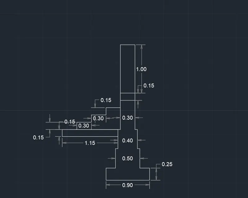
Aim: To Draw C.S of load bearing wall over spread footing using autocad.
Introduction: The spread footing is used shallow foundations.Over that we built load bearing wall.
Procedure:
1.First we have to draw pcc bed as of sizes 0.90X0.25.
2.Using line command with coordinates 0,0 as starting point.
3.The next point of (@0.90,0),(@0,0.25),(@-0.90,0),(@-0.25,0).
4.The next point using line command of coordinate (0.2,0.25) next point as (@0,0.4),(@0.05,0),(@0,0.4),(@0.30,0),(@0,-0.4),(@-0.5,0
),(@0,-0.4).
5.We got the stepped footing of sizes as 0.5 and 0.4.
6.From that we are drawing spread footing as in fig 1.
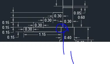
7. The footing of sizes 0.3X0.6 and with that draw spread footing from point 1.
8. The bed of length using line command as (@-1.15,0),(@0,0.15),(@1.15,0).
9. From the Frist step using line command (@0,0.15),(@0.30,0),(@0,0.15),(@0.30,0),(@0,0.15,0),(@0.30,0).
10. Then we got the steps of the footing.
11. Over the footing Damp proof layer of 0.05 is drawn.
12. Then we draw the load bearing wall over the damp proof coarse.
13. The sizes of wall is 0.30X1.
14. Then from the DPC using line command draw line of (@0,1),(@0.30,0),(@0,-1).
15. Then using this commands we can draw the C.S of load bearing wall over spread footing.
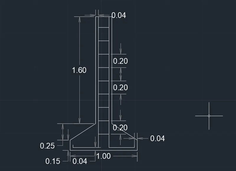
Aim: To draw C.S of Isolated footing using autocad.
Introduction: The isolated footing is the sloped footing to bear heavy load.
Procedure:
1. Using line command using coordinates as 0,0 as the starting point.
2. The next point as (@0,0.15),(@0.45<34D),(@0,1.60),(@0.25,0),(@0,-1.60),(@0.45<146D),(@0,-0.15),(@-1.0).
3. Using line command we can draw the reinforcement.
4. The coordinates of 0.04,0.04 as starting point.
5. Next points as (@0.38,0),(@0,1.85),(@0.16,0),(@0,-1.85),(@-0.38,0).
6. Then using offset command we can draw the offset of spacing of 0.20 units in vertical column as shown in the figure.
7. Using this tools and coordinates we can draw the isolated footing.
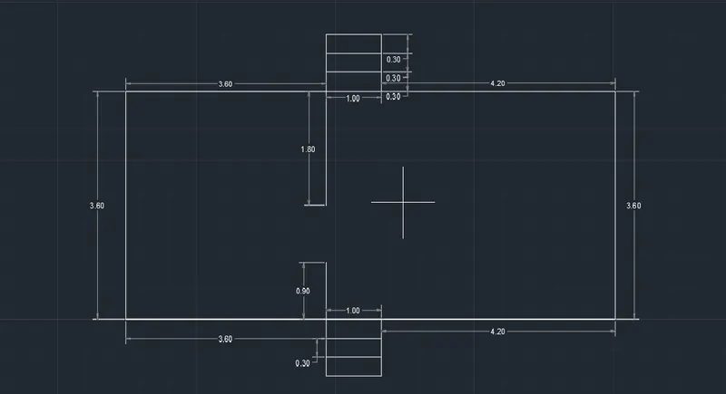
Aim: To draw the Line diagram of two bedroom building using autocad.
Introduction: The two bed room is drawn using coordinates in autocad.
Procedure:
1. The line tool is used with coordinates of starting point as 0,0.
2. Then from the second point as (@0,3.6),(@3.6,0),(@0,0.3),(@0,0.3),(@0,0.3),(@1,0),(@0,-0.9),(@4.2,0),(@0,-3.6),(@-4.2,0),(@0,-0.9),(@-1,0),(@0,0.9),(@-3.6,0).
3. And the we got the closed line of the building.
4. We have to divide the steps of 0.3 of thickness as shown in figure.
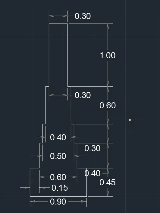
AIM : To draw C.S of load bearing wall showing foundation details.
Introduction : In this Cross section we are having pcc bed, footing and load bearing wall.
In this type footing is stepped footing and sizes of footing and wall are as follows.
procedure :
1. In this first we use line command using 0,0 as starting point.
2. Next using line command use coordinate as (0.90,0), next coordinate (@0,0.45) , (@0.90,0) and enter c for close.
3. Using line command use starting coordinate as (0.15,0.45) and next point as (@0,0.40) next points as (@0.05,0) , (@0,0.30) , (@0.05,0) , (@ 0,0.60).
4. Next point as (@0.30,0) and next points as follows (@0,-0.60),(@-0.05,0),(@0,-0.30),(@-0.05,0) and last point as (@0,-0.40).
5. And we got the stepped footing as 0.6,0.5,0.4 of sizes.
6. Next for the load bearing wall use line command coordinates of (0.30,1.75) next point as (@0,1.6),(@0.30,0) and last coordinate as (@0,-1.6).
7. Then we got the required size of load bearing wall.
8. Here we get the C.S of load bearing wall with foundation details.
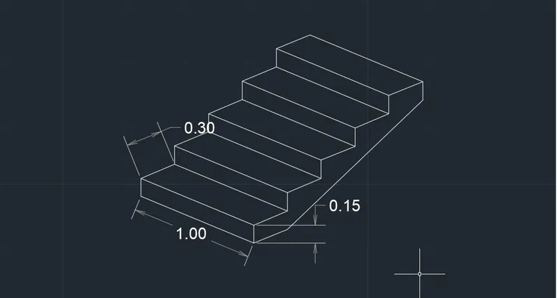
Aim: To draw the Isometric view of steps using autocad.
Introduction: The steps are used to travel from floor to floor. In this the isomteric view is drawn using isodraft tools.
Procedure:
1.Using Isodrafting tools we an draw the isometric view of steps.
2.Using Isoplane right we can draw the right side planes like thread of the steps as shown in figure.
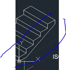
3.Using isoplane left we can draw the left side planes like width of the steps as shown in figure.
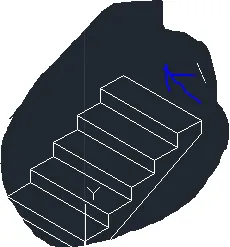
4.Using isoplane top we can draw the top layer of steps like theads and width as in the figure.
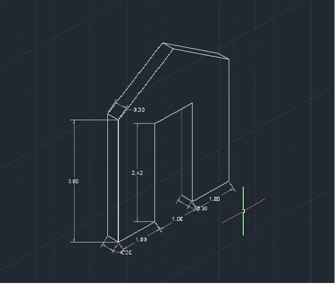
Aim: To Draw the Isometric view of Gable wall using autocad.
Introduction: The Gable wall is constructed below the pitched roof houses. the pitched roof is a sloped roof as they are used mostly in
the areas like heavy snow, heavy rain fall,and in earthquack zones.
Procedure:
1.The Isometric view is drawn by using Isometric drafting tools.
2.The First using right isoplane draft we draw the right side face is the room, the gable wall and door opening.
3.Then using left isoplane draft we have drawn thickness of the walls.
4.Then with isoplane top draft we can draw the opening head as shown in figure 1.