Drafting of various geometries using Chamfer, Fillet tool in AutoCad
Aim:
To create the decimal geometry by using line and circle.
Procedure:
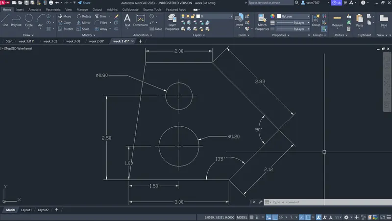
- Using line tool enter the first point as 1,1 and next point @3,0 and enter the next point @2.12<45
- Then enter the next point of the line @2.83<135 deg and enter the next point @-2,0
- Then close the line. The outer line is created.
- Then using circle use center diameter enter the center point of the circle 2.5,2 and enter the diameter 1.20
- Again using the circle center diameter method enter the center point of the circle 2.5,3.25 and enter the diameter 0.80
Result:
The decimal geometry is created by using the line and circle tool.
Aim:
To create the architectural geometry by using line tool.
Procedure:
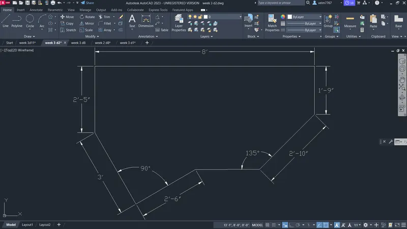
- Using line tool specify the first point. The top left corner is the first point.
- Then enter the next point @8',0 and enter the next point @0,-1'9''
- Then enter the next point @2'10''<225
- Now by using line specify the first point as the first point of the geometry created.
- Then enter the next point of the line @0,-2'5'' and next point of the line @3'<300
- Now by using construction line create a line of 90 deg inclination with reference to the previous line.
- Then using line tool specify the first point at the last line end point and enter the next point by using direct distance entry method 2'6''. Then erase the construction line.
- Finally using line tool connect the two point.
Result:
The architectural geometry is created by using line and construction line tool and using relative coordinate, direct distance entry method.
Aim:
To create engineering geometry by using line and circle tools.
Procedure:
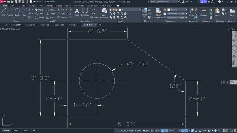
- Set the units as engineering.
- Using line tool enter the first point of the line 1',1' and enter the next point of the line @5'0.1'',0
- Then enter the next point of the line @0,1'6''
- Then using line tool specify the first point as the first point of the geometry and enter the next point @0,3'3''
- Enter the next point of line @2'6.5'',0 and join the discontinued line of the geometry.
- Then by using circle tool use center diameter method enter the center point as 2'3'',2'6'' and diameter as 1'6''
Result:
The engineering geometry is created by using the line and circle tool and using absolute and relative coordinate system.
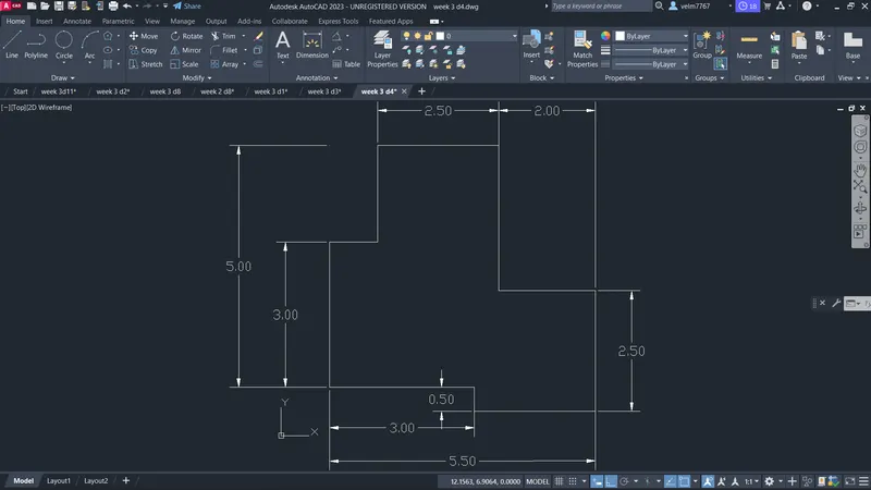
Aim:
To create the geometry by using line tool.
Procedure:
- Using line tool enter the first point of the line as 1,1 and enter the next point @3,0
- Then enter the next point of the line @0,0.5 and next point @2.5,0 and @0,2.5
- Then enter the next point @-2,0 and next point @0,3 and next point @-2.5,0
- Then enter the next point @0,-2 and next point @-1,0
- Finally colse the line by type C in the command line.
Result:
The geometry is created by using line tool and using relative coordinate system.
Aim:
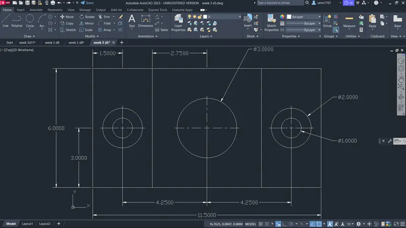
To create the geometry by using line and circle tool.
Procedure:
- Using line tool enter the first point as 1,1 and continue the line by entering the next points as @11.50,0, @0,6 and @-11.50,0. Finall close the line by typing C in the command line.
- offset the left side line through a distance of 3 units and the offseted line at 5.75 units.
- Using circle choose center diameter enter the center point of the circle as 2.5,4 and diameter as 2 unit. using the same center point enter the diameter of the circle 1 unit.
- Using circle choose center diameter enter the center point of the circle as 6.75,4 and diameter as 3 unit.
- Using circle choose center diameter enter the center point of the circle as 11,4 and diameter as 2 unit. using the same center point enter the diameter of the circle 1 unit.
Result:
The geometry is created by using the line tool and circle by using center diameter method.
Aim:
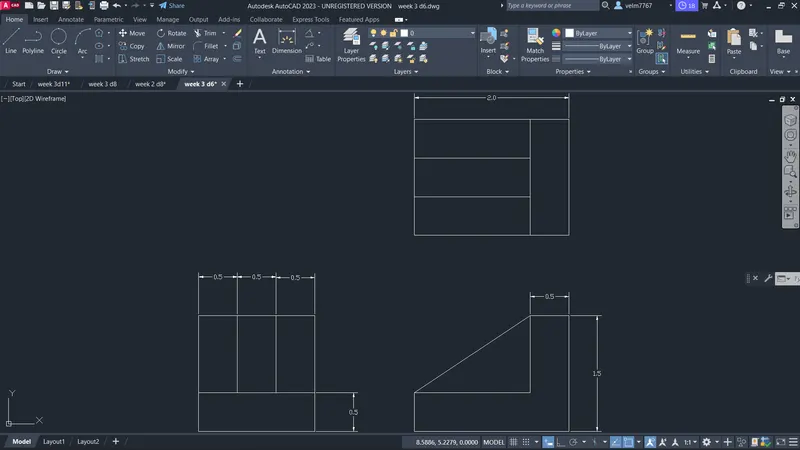
To create the geometry front view, side view and top view by using rectangle tool.
Procedure:
- Using rectangle command specify the first point and enter the second point @1.5,1.5 and offset the bottom, left and right side as 0.5 unit.
- Now trim the unwanted line in the geometry. Front view of the geometry is created.
- Using rectangle command specify the first point and enter the second point @2,1.5 and offset the bottom and right side as 0.5 unit.
- joint the two offsets by using line.
- Now trim the unwanted line in the geometry. side view of the geometry is created.
- Using rectangle command specify the first point and enter the second point @2,1.5 and offset the top, bottom and right side as 0.5 unit.
- Now trim the unwanted line in the geometry. Top view of the geometry is created.
Result:
The front view, side view and top view of the geometry is created by using the rectangle tool, offset and trim command.
Aim:
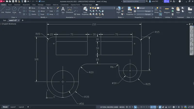
To create the geometry by using line, circle, xline and fillet command.
Procedure:
- Create the rectangle as the first point 1,1 and second point of the rectangle @210,135
- Insert a point using from option to create a point at 35 units in the y-axis.
- Using start, center, angle arc option, create a arc form the point, center as 35 units and angle of 180 deg.
- From the end of arc crrate a line at a distance of 40 units and next point of the line @90,0 and @0,-15
- From the end point of the line, create arc by using start, center, angle center point as 25 units and angle of 180 deg.
- Using circle tool take a center point as the arc center point and make a circle of diameter 50 units.
- Using circle tool take a center point as the arc center point and make a circle of diameter 30 units.
- Using fillet tool, fillet the top two coners of the rectangle of radius 15 units and bottom of radius 20 and 6 units.
- Then using construction line make a vertical line at the first point of the rectangle and offset it through the following distances 20,70,30,70 units.
- Then the top of the rectangle create a construction line and offset through the following distances 10,30,20 units.
- Finally using the trim command trim the unwanted lines of the rectangle.
Result:
The geometry is created by using the rectangle, construction line, circle, arc and fillet command.
Aim:
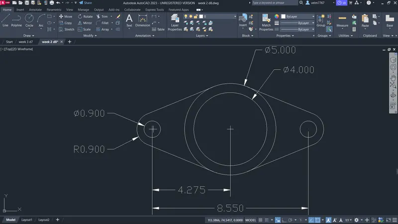
To create the geometry by using the circle and line tool.
Procedure:
- USing the circle command specify the center point of the circle and diameter of 5 units.
- Then using the same center point and enter the diameter of the circle as 4 units.
- Then create a reference line from the center point and create a line at a distance of 4.275 units in the positive and negative X-axis.
- Using the end point of the line as center create a circle of diameter of 0.9 units.
- Then using line create a tangent line form the top of the circle and bottom of the circle to the aprox distance from the center point of the circle orthogonally.
- Then using mirror command mirror the lines created.
- Finally using the fillet command, fillet the two edges of the line of radius 0.9 units.
Result:
The geometry is created by using the circle, line and fillet command.
Aim:
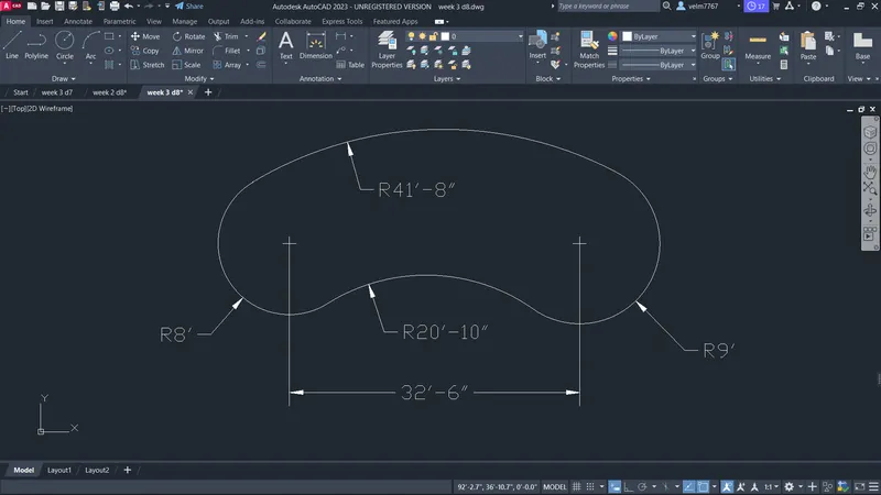
To create the bean shaped geometry by using circle tool.
Procedure:
- Using line tool create a reference line at a distance of 32'6''
- Then using circle command, use the first end point of the line as a center and create the circle of radius 8'
- Again using circle command, use the first end point of the line as a center and create the circle of radius 9'
- Then using the tan tan radius option of circle make the tangent point at the bottom of the two circles and radius of 20'10'' create a circle.
- Again using the tan tan radius option of circle make the tangent point at the top of the two circles and radius of 41'8'' create a circle.
- Finally using trim command trim the unwanted lines of the circle.
Result:
The bean shaped geometry is created by using the circle and trim command.
Aim:
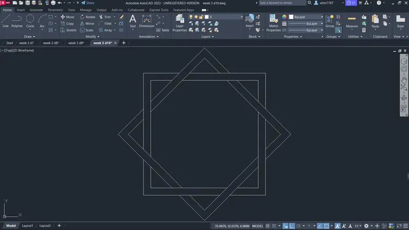
To create the geometry of the frame liked object by using polygon tool.
Procedure:
- Using polygon tool enter the sides as 4, specify the center pont and make the polygon inscribed of radius 6 units.
- Then using offset, offset the polygon through a distance of 0.5 units.
- Then using rotate tool rotate the polygon at an angle of 45 deg.
- Finally using the trim tool, trim the unwanted line in the polygons.
Result:
The frame liked geometry is created by using the polygon, offset, rotate and trim tools.
Aim:
To create the geometry by using the line and rectangle tool.
Procedure:
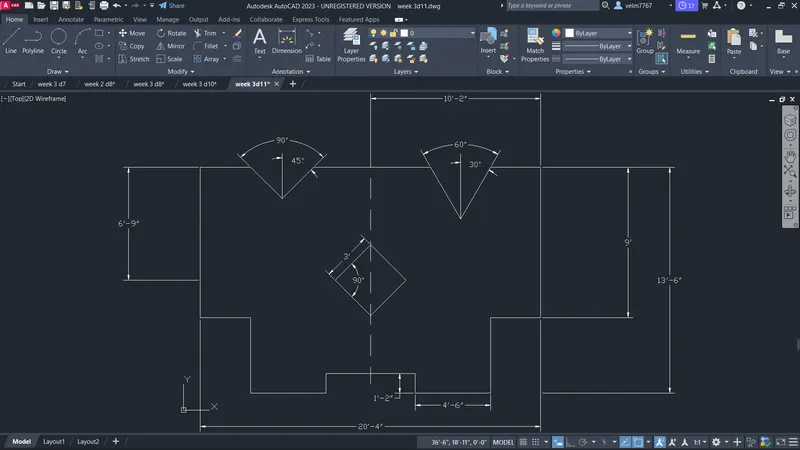
- Using line tool enter the first point of the line 4',1' and enter the next point of the line @4'6'',0
- Then enter the next point of the line @0,1'2'' and next point @5'4'',0
- Then enter the next point @0,-1'2'' and enter the next point @4'6'',0
- Enter the next point of the line @0,4'6'' and next point @3',0
- Then enter the next point @0,9' and @-3',0 and enter the next point @3'7''<240 and @3'7''<120
- Then enter the next point @-7',0 and enter the next point @2'8''<225 and @2'8''<135
- Then enter the next point @-3',0 and next point @0,-6'9''
- Then enter the next point @3',0 and close the line by typing C in the command line.
- offset the right side of the geometry through a distance of 10'2'' and top size through a distance of 6'9''
- Then create a rectangle specify the first point and second point @3',3'
- finally by using object snaping rotate the rectangle at 45 deg and place it at the intersection of the line offseted.
- Using erase command erase the offseted lines.
Result:
The geometry is created by using the line and rectangle tool and tirm, offset command.