Creating a Floor plan, Footing detail and Isometric view using AutoCad
Aim:
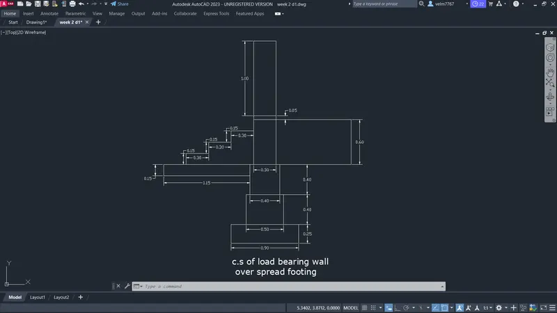
To create C.S. of load bearing wall over spread footing by using line and rectangle commands.
Procedure:
- Open the Autocad software and open new drawing and set the unit as imperial.
- Using the rectangle command enter the first point 1,1 and enter the second point by using the relative coordinate system @0.9,0.25
- Use the rectangle command enter the first point of the rectangle @-0.2,0 and enter the second point of the rectangle @-0.5,0.4
- Then use the rectangle command enter the first point @0.05,0 and enter the second point of the rectangle @0.4,0.4
- Again using the rectangle command enter the first point of the rectangle @-0.05,0 and enter the second point of the rectangle @-0.3,0.6
- Then useing the rectangle command enter the first point of the rectangle @0,0 and enter the second point @0.3,0.05
- Again using the rectangle command enter the first point of the rectangle @0,0 and enter the second point of the rectangle @-0.3,1. Now the steps of the footing and the wall is created.
- By using the rectangle command enter the first point by using absolute coordinate system 1.6,2.05 and enter the second point @1,0.6. Now the basement wall is created.
- Then by using rectangle command enter the first point 1.25,2.05 and enter the second point @-1.15,-0.15
- Now by using the line command enter the first point of the line 1.3,2.5 and enter the next point @-0.3,-0.15. Then enter the next point @-0.3,-0.15 and next point @-0.3,-0.15.
Result:
The C.S. of load bearing wall over spread footing is created by using the absolute and relative coordinate system and by using the commands line and rectangle.
Aim:
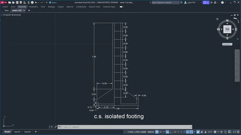
To create the C.S. of isolated footing by using rectangle, chamfer and copy command.
Procedure:
- Using the rectangle command by absolute coordinate system enter the first point 1,1 and by using relative coordinate system enter the next point of the rectangle @1,0.4
- By using the chamfer command chamfer the two top corners of the rectangle by entering the chamfer point 0.38,0.25. The sloped footing is created.
- Then by using absolute coordinate enter the first point of the rectangle 1.38,1.4 and enter the second point by using the relative coordinate @0.24,1.6. Now the column is created.
- Then by using absolute coordinate create a line and enter the first point 1.04,1.04 and by using relative coordinate enter @0.38,0 and @0,1.96. Now the left side of the vertical reinforcement is created.
- Then by using the line command enter the first point of the line 1.96,1.04 and enter the next point as @-0.38,0 and then enter the next point @0,1.96. Now the right side of the reinforement is created.
- By using the line command enter the first point 1.42,1.20 and enter the next point @0.16,0. The stirrup is created.
- Then by using copy command seclect the stirrup and select the base point then choose array option and enter the 9 number of copies then enter the distance as 0.2. The stirrups is created.
Result:
The C.S. of isolated footing is created by using the rectangle, chamfer and array by using copy command.
Aim:
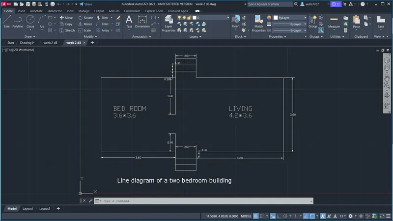
To create a line diagram of a two bedroom building by using rectangle and line.
Procedure:
- Using absolute coordinate enter the first point of the rectangle 1,2 and enter the second point of the rectangle @8.8,3.6. The outer line of the plan is created.
- Now create the steps by using the rectangle command. By using the absolute coordinate enter the first point of the rectangle 4.6,2 and by using relative coordinate enter the next point of the rectangle @1,-0.3
- Then copy the first step and create 2 more copies. The steps in the lower part is created.
- Then by using rectangle command enter the first point of the rectangle 4.6,5.6 and enter second point of rectangle @1,0.3
- Then copy the first step and create 2 more copies. The steps in the upper part is created.
- Now by using line by absolute coordinate enter the first point 4.6,2 and by using direct distance entry method enter the distance 0.9 in y-axis.
- Using the line command enter the first point 4.6,4.5 and by using the direct distance entry method enter the distance 1.8 in the negative y-axis.
Result:
The line diagram of a two bedroom building is created by using rectangle, line and by using the commands copy and direct distance entry method.
Aim:
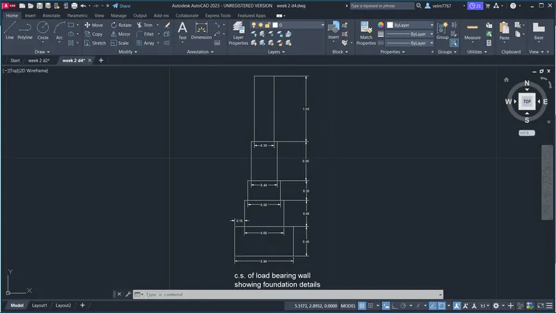
To create C.S. of load bearing wall showing foundation deatails by using rectangle.
Procedure:
- Using the rectangle command enter the first point 1,1 and enter the second point of the rectangle @0.9,0.45
- Then by using the rectangle enter the first point by using relative coordinate @-0.15,0 and enter the second point @-0.60,0.4
- By using the rectangle command enter the first point @0.05,0 and enter the second point @0.5,0.3
- Then by enter the first point of the rectangle @-0.05,0 and enter the second point of the rectangle @-0.4,0.6
- Finally by using rectangle enter the first point @0.05,0 and enter the second point @0.3,1
Result:
The C.S. of load bearing wall showing foundation details is created by using rectangle.
Aim:
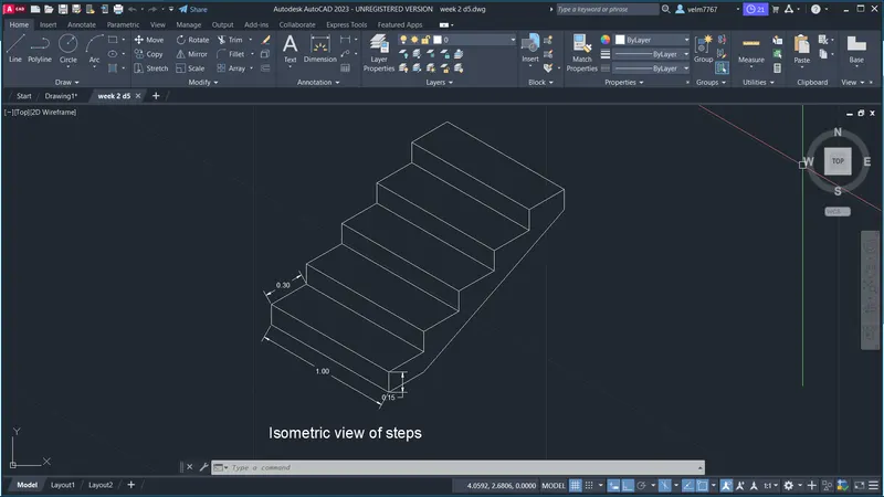
To create isometric view of steps by using isometric drafting.
Procedure:
- Trun on the isometric snap by using the command DS (drafting settings)
- Make sure that the orthomode is on.
- Using line command enter the first point 1,1 and turn on the isoplane left and by using direct distance entry method enter the distance 1 and 0.15
- Then switch the isoplane right enter the distance 0.3
- Then copy the riser and thread create 4 copies of steps.
- Then using line command by absolute coordinate enter the first point 1,1 and by direct distance entry method enter the next points 0.15 and 0.3
- Then copy the riser and thread create 4 copies of steps.
- Now copy the center line of the step and create 10 copies it will create a steps.
- Then by using line command enter the first point 1,1 and next point 0.3
- Again using line pick the last step and create a line downwards of distance 0.15
- Finally using line connect the two line to create bottom of the waist slab.
Result:
The isometric view of steps is created by using the isometric drafting and command lines and copy.
Aim:
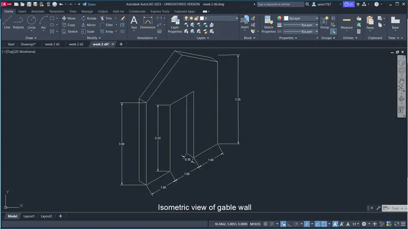
To create isometric view of gable wall by using isometric drafting.
Procedure:
- Trun on the isometric snap by using the command DS (drafting settings)
- Make sure that the orthomode is on.
- Select the isoplane right and use line to enter the first point 1,1 and enter the next point by using the direct distance entry method 1 and then enter the next point 2.42 in the upward direction and enter the next point 2.42 in the downward direction and then enter the next point 1 in the right side and enter the next point 3 in the upward direction.
- Next by using the absolute coordinate enter the first point of the line 1,1 and enter the next point in the upward direction by direct distance entry method as 3. Now the front facing of the wall is created
- Now make a refernce line from the center point of the door and enter the distance of 1.58. Connect the lines form the outer top point of the walls and errase the reference line. The pitched roof above the gable wall is created.
- Then using line to create a line of distance 0.3 in the isoplane left and connect the line in the top of the door
- Then switch to isoplane left and create a line of distance 0.3 form the starting point of the wall and enter the next point distance of the line as 3. Then copy the base line of distance 0.3 and place it in the first corner, middle top and last corner.
- Finally copy the sloped lines and place it the copied lines last corner.
Result:
The isometric view of gable wall is created by using isometric drafting and by using lines and copy command.