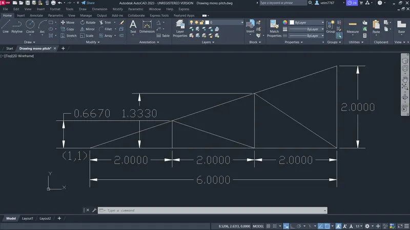
Creation of geometries by Coordinate system methods using AutoCad
Aim:
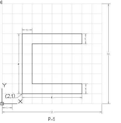
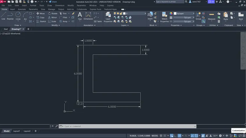
To create the geomentry of using all coordintes system methods. Line tool is used to create the geomentries.
Procedure:
- Open the Autocad software, then go to the quick setup choose imperial template and decimal units.
- use line tool in the ribbon or type l in the command line.
- Enter the first point 2,1
- By using the relative coordinate enter the next point @0,6
- Then by using the relative coordinate enter the next point @6,0
- Then by using the relative coordinate enter the next point @0,-1
- Then by using the relative coordinate enter the next point @-5,0
- Then by using the relative coordinate enter the next point @0,-4
- Then by using the relative coordinate enter the next point @5,0
- Then by using the relative coordinate enter the next point @0,-1
- finally close the line by using the command line.
Result:
The given geomenty is created by using the lines. Relative coordinate system is used to create this geomentry.
Aim:
To create the geomentry of using all coordintes system methods. Line tool is used to create the geomentries.
Procedure:
- Open the Autocad software, then go to the quick setup choose imperial template and decimal units.
- use line tool in the ribbon or type l in the command line.
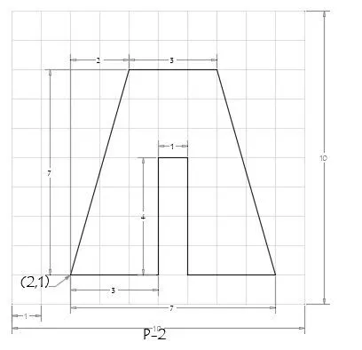
- Enter the first point 2,1
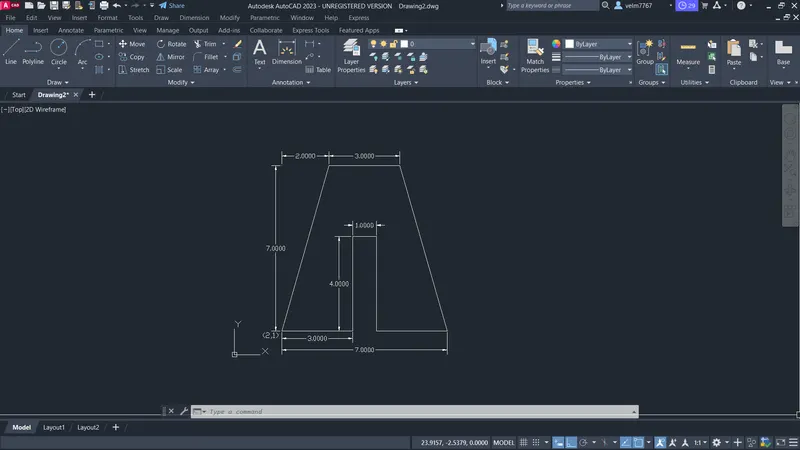
- By using the relative coordinate system enter the next point @2,7
- Enter the next point @3,0
- Enter the next point as 2,-7
- Then enter the next point @-3,0
- Enter the next point @0,4
- Next point @ -1,0
- Then next point @0,-4
- Finally close the line by using the command line.
Result:
The given geomenty is created by using the lines. Relative coordinate system is used to create this geomentry.
Aim:
To create the geomentry of using all coordintes system methods. Line tool is used to create the geomentries.
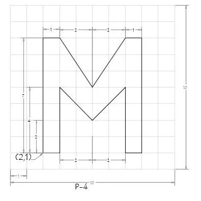
Procedure:
- Open the Autocad software, then go to the quick setup choose imperial template and decimal units.
- use line tool in the ribbon or type l in the command line.
- Enter the first point 2,1
- By using the relative coordinate enter the next point @0,7
- Then enter the next point @1,0
- Enter the next point @2,-3
- Next point @2,3
- Then enter the next point @1,0
- The next point @0,-7
- Enter the next point @-1,0
- Then the next point @0,4
- Then enter the next point @-2,-2
- The next point @-2,2
- Then the next point @0,-4
- Finally close the line by using the command line.
Result:
The given geomenty is created by using the lines. Relative coordinate system is used to create this geomentry.
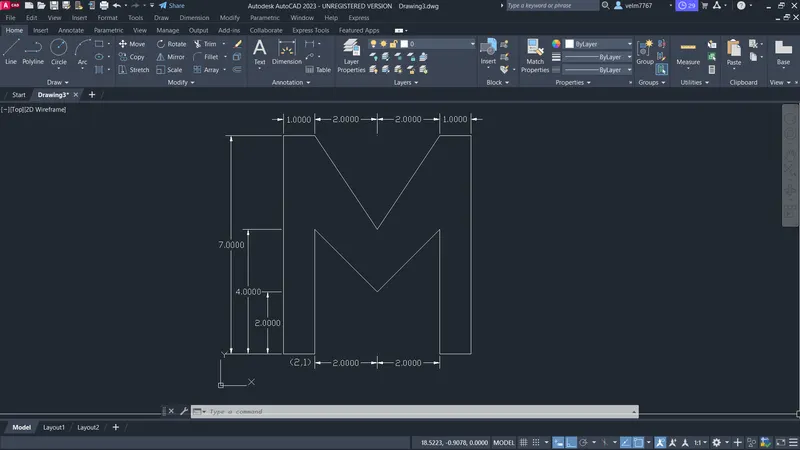
Aim:
To create the geomentry of using all coordintes system methods. Line tool is used to create the geomentries.
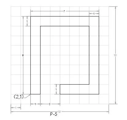
Procedure:
- Open the Autocad software, then go to the quick setup choose imperial template and decimal units.
- use line tool in the ribbon or type l in the command line.
- Enter the first point 2,1
- By using the relative coordinate enter the next point @0,8
- Then enter the next point @0,8
- Then by using the relative coordinate enter the next point @7,0
- Then enter the next point @0,-8
- Enter the next point @-4,0
- Enter the next point @0,1
- Then enter the next point @3,0
- Enter the next point @0,6
- Then enter the next point @-5,0
- Enter the next point @0,-7
- Finally close the line by using the command line.
Result:
The given geomenty is created by using the lines. Relative coordinate system is used to create this geomentry.
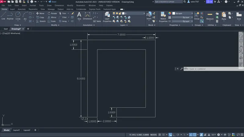
Aim:
To create the geomentry of using all coordintes system methods. Line tool is used to create the geomentries.
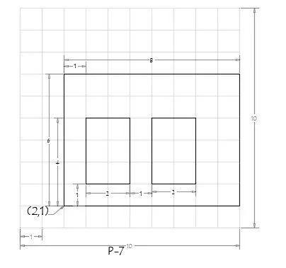
Procedure:
- Open the Autocad software, then go to the quick setup choose imperial template and decimal units.
- use line tool in the ribbon or type l in the command line.
- Enter the first point 2,1
- Then by using the relative coordinate enter the next point @0,6
- Enter the next point @8,0
- Then enter the next point @0,-6
- Then close the line by using the command line.
- Then by using the absolute coordinate system enter the point 3,2
- BY using the relative coordinate enter the next point @0,3
- Enter the next point @2,0
- Then enter the next point @0,-3
- Then close the line by using the command line. The first box in the inner side will be created.
- Then by using the absolute coordinate system enter the point 6,2
- BY using the relative coordinate enter the next point @0,3
- Enter the next point @2,0
- Then enter the next point @0,-3
- Then close the line by using the command line. The second box in the inner side will be created.
Result:
The given geomenty is created by using the lines. Relative coordinate system is used to create this geomentry.
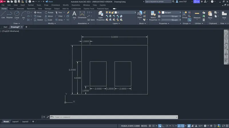
Aim:
To create the geomentry of using all coordintes system methods. Line tool is used to create the geomentries.
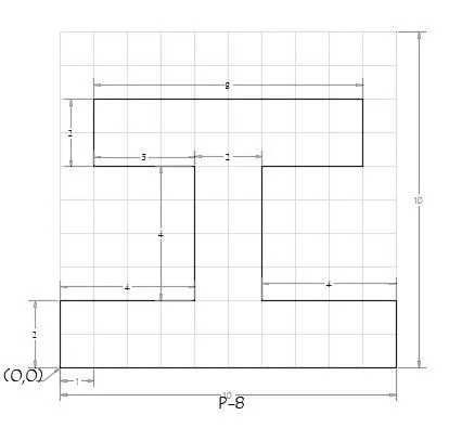
Procedure:
- Open the Autocad software, then go to the quick setup choose imperial template and decimal units.
- use line tool in the ribbon or type l in the command line.
- Enter the first point 0,0
- Then enter the next point by using relative coordinate system @0,2
- Then enter the next point @4,0
- Enter the next point @0,4
- Then enter the next point @-3,0 and @0,2 and enter the next point @ 8,0
- Then enter the next point @0,-2 and @-3,0 and enter the next point @0,-4
- Enter the next point @4,0 and @0,-2
- finally close the line by using the command line by typing c.
Result:
The given geomenty is created by using the lines. Relative coordinate system is used to create this geomentry.
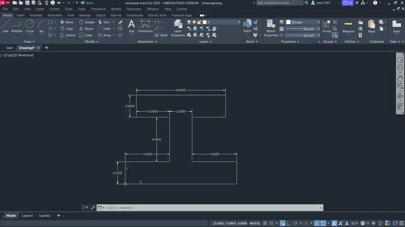
Aim:
To create the geomentry of using all coordintes system methods. Line tool is used to create the geomentries.
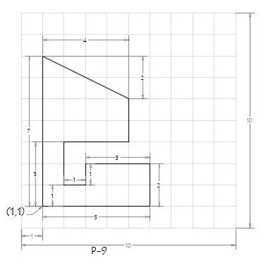
Procedure:
- Open the Autocad software, then go to the quick setup choose imperial template and decimal units.
- use line tool in the ribbon or type l in the command line.
- Enter the first point 1,1
- Then by using the relative coordinate enter the point @0,7
- Then enter the point @4,-2 and @0,-2
- Enter the point @-3,0 and @0,-2
- Then enter the value @1,0 and @0,1 and @3,0
- Enter the value @0,-2
- Finally close the line by using the command line by typing the letter c.
Result:
The given geomenty is created by using the lines. Relative coordinate system is used to create this geomentry.
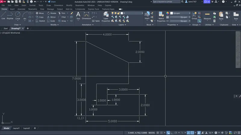
Aim:
To create the geomentry of using all coordintes system methods. Line tool is used to create the geomentries.
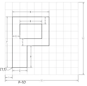
Procedure:
- Open the Autocad software, then go to the quick setup choose imperial template and decimal units.
- use line tool in the ribbon or type l in the command line.
- Enter the first point 1,1
- Then by using the relative coordinate system enter the point @0,7
- Then enter the point @5,0 and @0,-4
- Then enter the point @-3,0 and @0,-3
- Then close the line by using the command line by typing the letter c.
- Then by using the absolute coordinate system using line command and enter the point 2,5
- Then enter the point @0,2 and @3,0 and 0,-2
- finally close the line by using the command line by typing the letter c.
Result:
The given geomenty is created by using the lines. Relative coordinate system is used to create this geomentry.
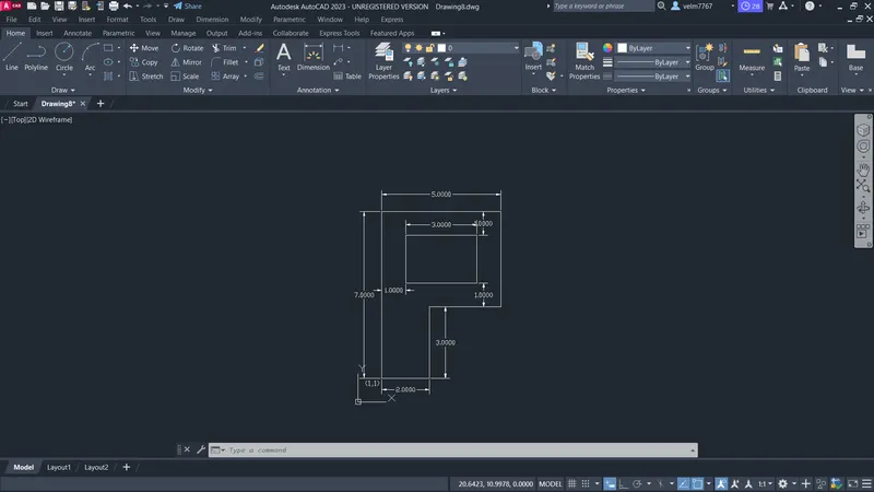
Aim:
To draw the profile by using the coordinate system methods.
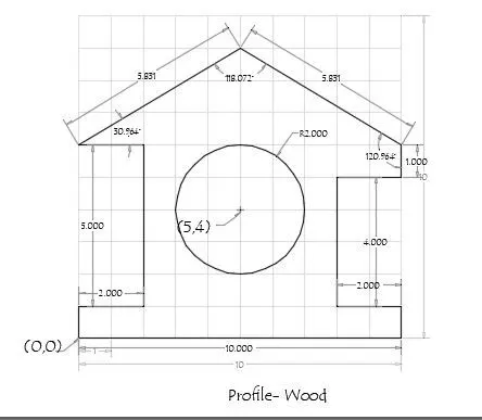
Procedure:
- Open the Autocad software, then go to the quick setup choose imperial template and decimal units.
- use line tool in the ribbon or type l in the command line.
- Enter the first point 0,0
- Now by using the relative coordinate method enter the next poin @0,1 and @2,0
- Then enter the next point @0,5 and -2,0
- Then enter the next point by using the polar coordinate method @5.831<30.964 and enter the next point @5<329.036
- Then by using the relative coordinate method enter the next point @0,-1 and @-2,0
- Then enter the next point @0,-4 and @2,0 and enter the next point @0,-1
- Now close the line by using the command line by typing the letter c.
- BY using absolute coordinate method draw circle enter the point @5,4 of radius 2 units.
Result:
The given profile is created by using the lines and circles. Relative coordinate system, absolute coordinate system and polar coordinate system is used to create this profile.
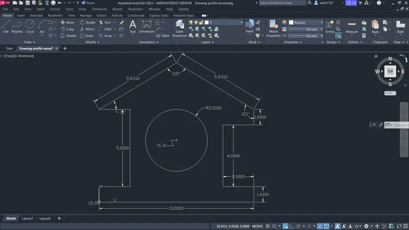
Aim:
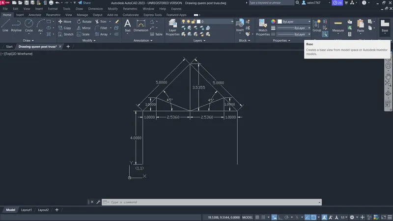
To draw the profile and truss by using the coordinate system methods.
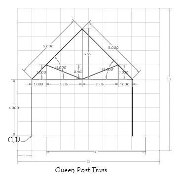
Procedure:
- Open the Autocad software, then go to the quick setup choose imperial template and decimal units.
- use line tool in the ribbon or type l in the command line.
- Enter the first point 1,1
- Then by using the relative coordinate system enter the next point @0,4
- Now by using the polar coordinate system enter the next point @5<45 and next point @5<315
- Enter the next point @0,-4
- Now by using the absolute coordinate system enter the point 1,5 and by using relative coordinate method enter the next point @7.112,0
- By using absolute coordinate method enter the point 2,5 and by using relative coordinate method enter the next point @2.536,-1
- Then enter the next point @2.536,1 and @0,-1
- By using absolute coordinate method enter the point 4.536,5 and by using the relative coordinate method enter the next point @0,3.536
Result:
The given profile and truss is created by using the lines . Relative coordinate system, absolute coordinate system and polar coordinate system is used to create this profile.
Aim:
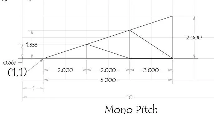
To draw the truss by using the coordinate system methods.
Procedure:
- Open the Autocad software, then go to the quick setup choose imperial template and decimal units.
- use line tool in the ribbon or type l in the command line.
- Enter the first point 1,1
- Then by using the relative coordinate method enter the next point @2,6 and @0,-2
- Now enter the next point @-2,1.333 and @0,-1.333
- Then enter the next point @-2,0.667 and @0,-0.666
- Now by using the absolute coordinate method enter the point 1,1 and by using the relative coordinate method enter the next point @6,0
Result:
The given truss is created by using the lines. Absolute and relative coordinate system methods is used to create this truss.