Creating a Residence Layout, Seating plan, Toilet and Utility room plan using AutoCad
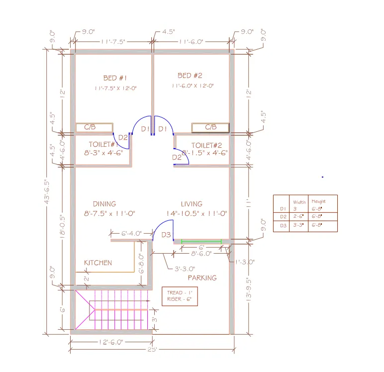
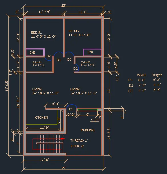
AIM:- To draw the layout of a residence as shown in the Figure 1. Consider all dimensions as reference to sketch the unit plan. Also the text in the layout are only for reference. Assume the missing dimensions. Also, refer the schedule for size of the doors.
INTRODUCTION:-
To draw this geometry, I have used several autocad commands like- line,circle, offset, trim,erase,hatch etc., and I set dimension (Engineering) in Autocad. Moreover, I set limits with command "Limits", specify the left corner points ans right corner points and then enter zoom all("z-a") in this drawing. Also, I used dimesion command for measuing the dimensions in Autocad along with text command to write drawing name.
PROCEDURE:-
Open Autocad and type a command "Unit" and press enter, then set unit as Engineering and set angle in degree- base angle is east -mark angle direction as anticlockwise. Type a command "DIMSTYLE" and press enter, then click to modify and go to primary unit tab and set it Engineering and set the precision to 0'-0.0" and cick ok.
- Draw construction lines by command "XL" for vertical line and again do it for horizontal line.
- Trim the left side and top portion of the construction line.
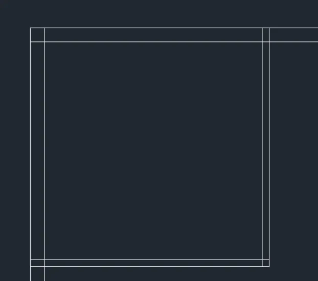
Drawing bed 1:-
- Take offset of both construction lines of 0'-9" by command "OFFSET" -give offset distance as 0'-9" in the command box.
- Then take the offset of 11'-7.5" to the +X direction and offset of 12'-0" downwards so that the room is formed.
- Again give offset to the both lines with 4.5", so that the wall thickness is created.
- Trim off the unwanted lines.
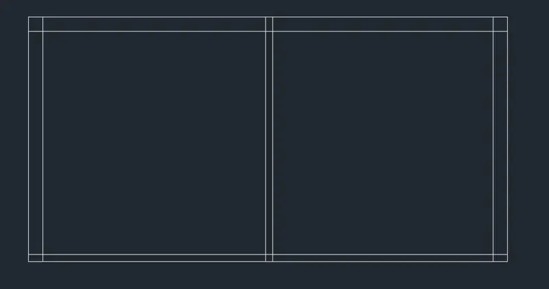
Drawing bed 2:-
- Give offset from the wall thickness of bed 1 towards +X direction of 11'-6".
- Offset the 0'-9" to create wall on right side.
- extend the line of 12' from bed 1 towards this line. Command -"EXTEND" and select the line to where it should be extended (4'-6.0" offseted line of bed 2), then select the line which is to be extended. (12'-0" line of bed 1, along with wall thickness).
- Trim off the rest of the line in +X direction and -Y direction. Command "TRIM" and double entered - Select the lines to be trimmed.
Drawing Toilet 1:-
- Offset 4'-6" downwards then also offset 0'-4.5" wall.
- Extend the left side wall towards the line 4'-6" and the wall.
- From that line offset 8'-3" towards +X direction and offset the wall of 0'-4.5" also.
- Trim off and erase all the unwanted lines.
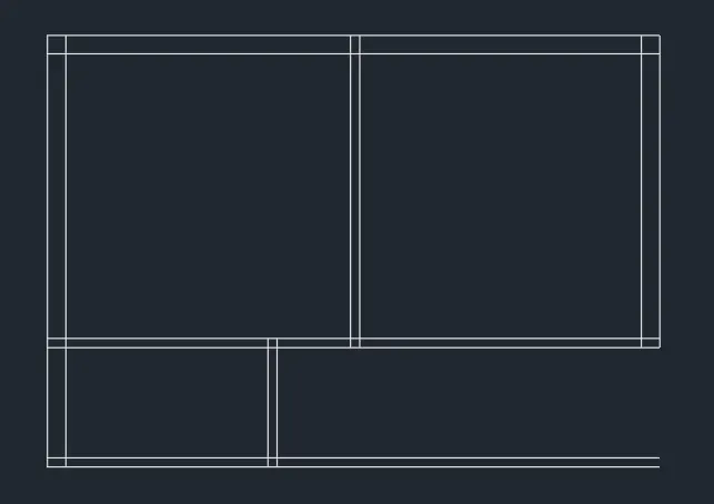
Drawing Toilet 2:-
- Extend the wall thickness of bed 2 to the line 4'-6" line (extention line of toilet 1)
- Offset a distance of 8'-1.5" towards -X direction and also 0'-4.5" wall thickness.
- Trim off the unwanted lines.
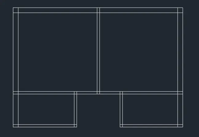
Drawing of dinning and living Room:-
- Give offset of 11'-0" from the wall of toilet and also the wall of 0'-9"
- Extend the left wall towards the 11' line and 0'-9" line.
- Use fillet to join this line and the wall of toilet 2.
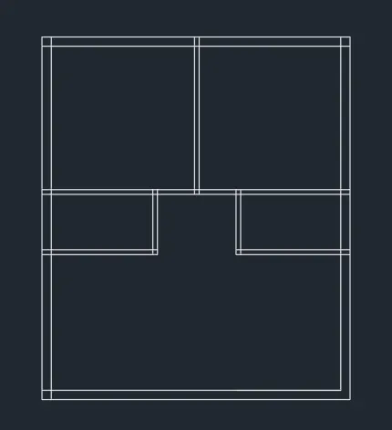
- Give offset of 8'-7.5"(from left side inner boundary) to understand the partition between the dinning and living.
- Trim off the wall thickness of dinning and offset it as 0'-4.5"
- Finally trim off all other unnecessary lines.
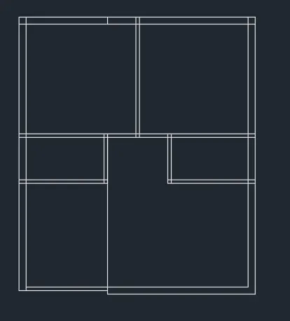
Drawing of Kitchen:-
- Give an offset from the dinning wall of 6'-8" and give an offset of 0'-9"
- Extend the left wall towards this line.
- Extend the right side dinning wall towards downward to kitchen wall
- Give an offset the wall thickness as 9" for newly drawn kitchen wall.
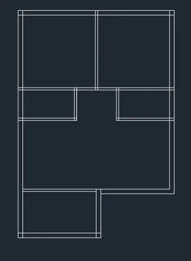
- Give offset 13'-9.5" from the living wall towards downward.
- Type "Extend" and press enter, then exten both right outside walls accordingly.
- Give offset of 6' from downside kitchen wall.
- Extend both left side outer wall line towards this line.
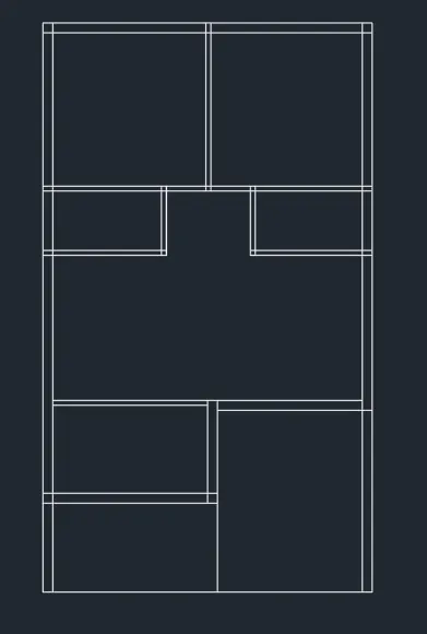
Drawing of Staircase:-
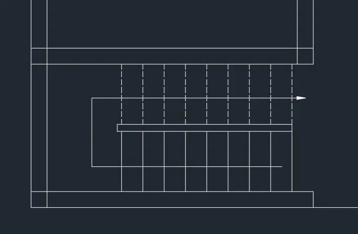
Given:- Thread 1' and Riser 6"
- Give a wall thickness of 9" for the staircase room.
- Divide the staircase room by giving offset of 3' from the front wall thickness.
- Give an offset of 0'-1.96" to show the handrail (Assumed 5cm is usually given).
- Erase the central line of handrail after offset for handrails.
- Give an offset of (1' for thread) to draw the stair in plan view.
- Draw 9 offsets as there are 9 risers for 8 steps.
- Trim off the lines between the handrails and give the other side as dotted lines (It indicates that it is the upward stair, not visible when viewing ground floor plan)
- For that select the lines and change the line type to ISO dash.
- Mark the direction of stairs with the help of "Qleader" command.
Drawing Doors:-
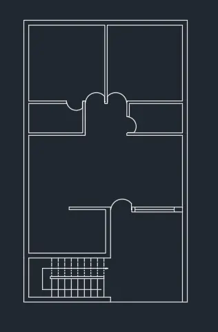
- Trim all the door openings with their respective width D1= 3', D2= 2'-6", D3= 3'-3".
- For open kitchen, trim the line retaining a distance of 6'-4" from right side of kitchen.
- Draw doors creating a hinge of 0'-0.5" from midpoint of both the wall, then drawing a circle with one point on the midpoint of one hinge and other the midpoint of other hinge.
- Type a command "offset" and then put a value 1'-3.0" from living room inside wall, again give a offset of 6'-0" from that lat offseted line and trim off the unnecessary lines.
- Using line command draw a line of 6'-0" from the center of the offseted line inside the wall thickness.
- Trim all the unwanted lines and fillet the corners with fillet radius zero. Command "Fillet" - Select both the lines (fillet radius is zero by default).
Drawing the kitchen slab and cupboard:-
- Offset a distance of 2' to make the kitchen slab, then trim off the unnecessary lines.
- Draw the cupboard by creating a rectangle command "REC"- Specify base point -Click on dimension- give dimension as 5'X2'.
- Copy the rectangle to other bedroom also.
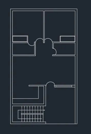
- Placing each component in layer.
- From layer property- create new layer- create 5 layers each for walls,doors, windows, stair, kitchen slab and cupboard.
- Name each layer as wall, door, windows, stair, kitchen slab and cupboard and assign different colours, so that it can be identified seperately.
- With the help of Hatch fill the wall with grey colour.
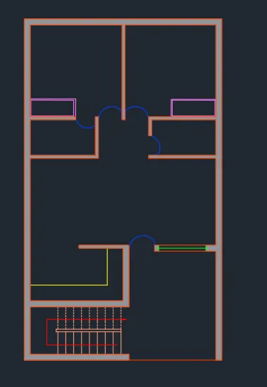
RESULT:-
FINAL SKETCH OF RESIDENCE BUILDING.
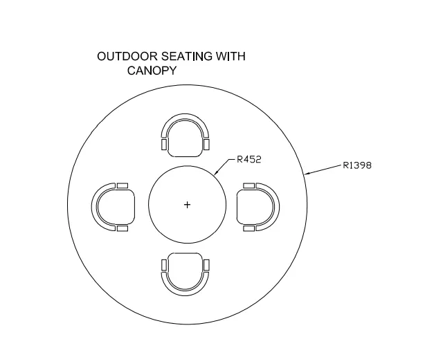
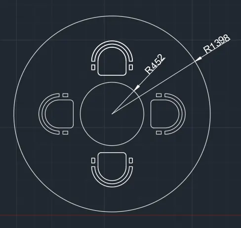
AIM:- Sketch the seating plan for an outdoor canopy. I have assumed the dimensions for the seating. Also, I have considered the dimensions in mm.
INTRODUCTION:-
To draw this seating plan, I have used several autocad commands like- line,arc, offset, trim,erase,extend etc., and I set dimension (Decimal) in Autocad. Moreover, I set limits with command "Limits", specify the left corner points ans right corner points and then enter zoom all("z-a") in this drawing. Also, I used dimesion command for measuing the dimensions in Autocad along with text command to write drawing name.
PROCEDURE:-
Open Autocad and type a command "Unit" and press enter, then set unit as Decimal and set angle in degree- base angle is east -mark angle direction as anticlockwise. Type a command "DIMSTYLE" and press enter, then click to modify and go to primary unit tab and set it Decimal and set the precision to 0.0 and cick ok.
- Select metric units as the dimension is in mm.
- Draw a circle with command "Circle" and select a center point, then give the radius as 1398 mm.
- Draw another circle with same center with radius 452 mm.
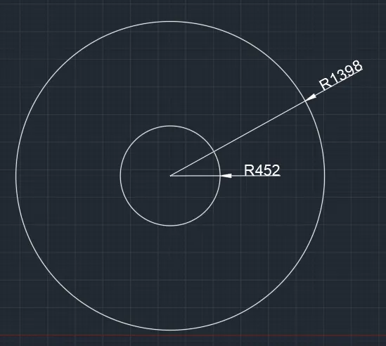
- Draw an offset of 300mm from the inner circle to determine the position of the chairs.
- Type a command "XLINE" for along the diameter of the bigger circles, then trim off the outside lines.
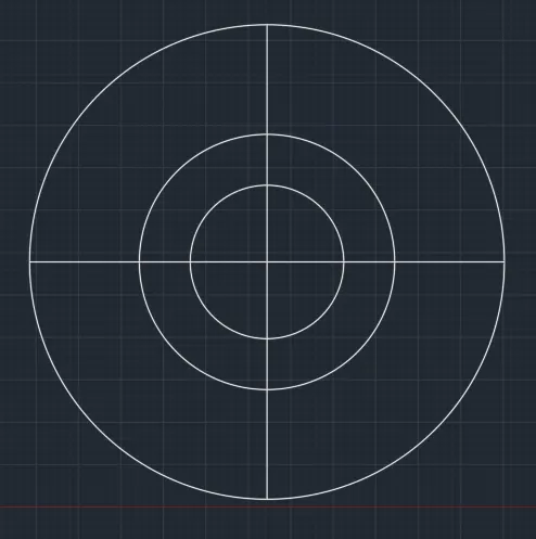
Drawing Chairs:-
- Draw a rectangle with command "REC" giving dimensions as 400 mm and 200 mm (@400,200).
- Draw an arc with start-center and end method with the with the end points and center of the side (400mm) of rectangle.
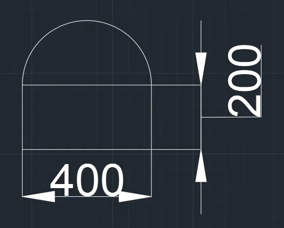
- Give two offsets of 45 mm outside the arc, Command "OFFSET" - Give distance as 50 and select the object and join the endpoints of the offseted arc.
- Draw another rectangle of 450mm X 70mm for the handle of the chair Command: "REC" select the base point and click on dimension and give as 45mm and 70mm.
- Copy it on the other side so that both handles are formed.
- Fillet the corner of rectangle by 45mm command "Fillet" - Give the fillet radius 50mm and select the two lines and trim off the unwanted line.
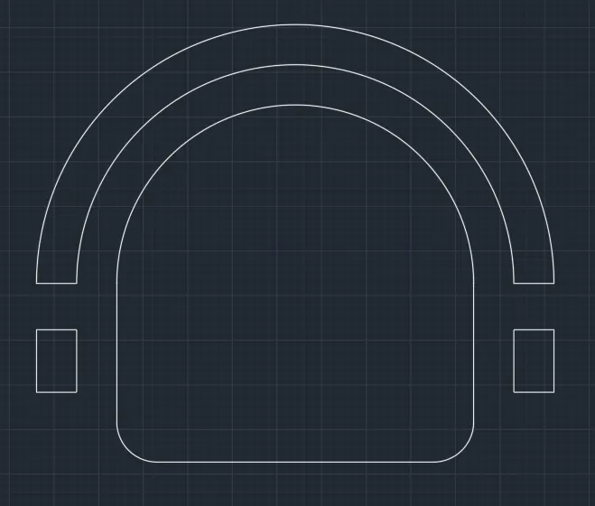
- Move the chair and place it such a way that it touches the offseted 200mm circle and the reference diameter line. Command "Move"- select the basepoint and move it.
- Mirror the chair to the opposite side - Command "Mirror" - select the base point and draw the reference line where we need to mirror without erasing the source object. Then move the mirroed chaired into opposite side.
- Rotate the chair and move it so that the chair in left side is created, command "ROTATE" then select the base point and rotate to desired angle.
- Again mirror the chair so as to create a chair in right side.
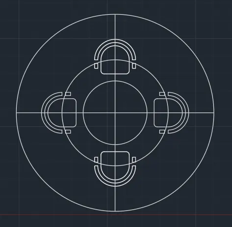
- Delete the unnecessary circle and lines
RESULT:-
FINAL SKETCH OF OUTDOOR SEATING WITH CANOPY.
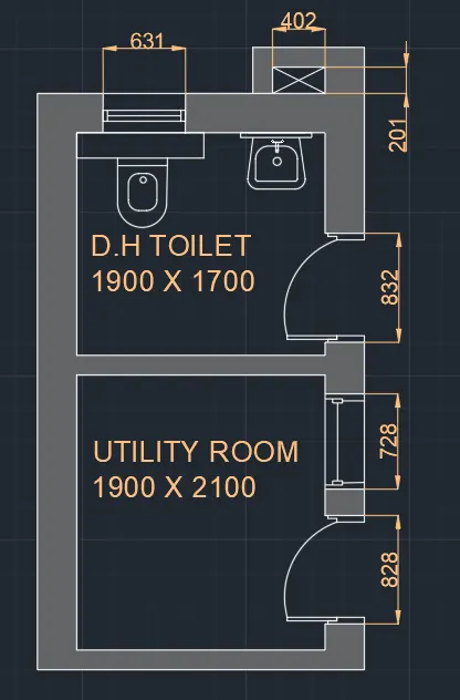
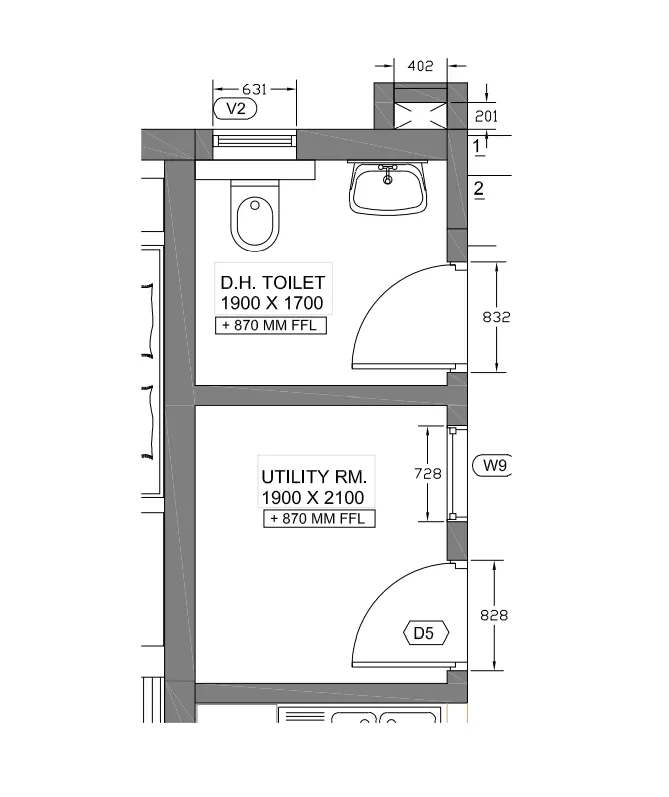
AIM:- To sketch the part plan for the toilet and utilities room. Consider the outer wall thickness as 300mm and inner wall thickness as 150mm. Also, assume the missing dimension, Texts, dimensions, and hatches are only for references. Also, symbols for toilets and w/c are also for references.
INTRODUCTION:-
To draw this part plan for the toilet and utilities room, I have used several autocad commands like- line,arc, offset, trim,erase,circle, hatch, rectangle,extend etc., and I set dimension (Decimal) in Autocad. Moreover, I set limits with command "Limits", specify the left corner points ans right corner points and then enter zoom all("z-a") in this drawing. Also, I used dimesion command for measuing the dimensions in Autocad along with text command to write drawing name.
PROCEDURE:-
Open Autocad and type a command "Unit" and press enter, then set unit as Decimal and set angle in degree- base angle is east -mark angle direction as anticlockwise. Type a command "DIMSTYLE" and press enter, then click to modify and go to primary unit tab and set it Decimal and set the precision to 0.0 and cick ok.
- Draw construction lines by command "XL" for vertical line and again do it for horizontal line.
- Trim the left side and top portion of the construction line.
Drawing Utility Room:-
- Draw an offset of 300mm from the left side of vertical construction line and the offset of 150mm from the bottom horizontal construction line.
- Draw an offset of 210mm upwards and offset of 1900mm towards the right side and give the wall thickness of 150mm and 300mm respectively.
Drawing D.H Toilet:-
- Draw an offset by command "OFFSET" of 1700mm upwards and wall thickness of 300mm as it is the external wall, and a room is formed.
- Trim off the rest of the construction lines.
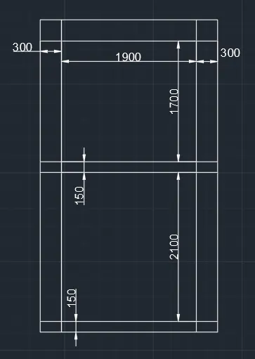
- Create opening for doors.
- In utilities room offset a distance of 200mm from the wall and then give an offset of 828mm (opening), and trim it so that opening has to be created. Also, give an another offset of 200mm and another offset of 728mm for window in utility room. Draw central line for window.
- Trim off the unnecessary lines.
- For toilet, after an offset of 100mm, give another offset of 832mm and trim to form the opening.
- Create the door by creating the hinge of 12.5mm, then draw a circle to the midpoint of other side of wall. Trim off the rest of circle to form an arc.
- Draw ventilator window of 631mm in toilet room after an offset of 200mm from left side wall.
- Draw the duct shown behind the toilet room by offseting 201 mm and 150 mm wall thickness upwards, and extend the lines from main wall towards last offseted line.
- Extent the wall of toilet towards it and offset 402 mm, offset wall thickness as 150 mm.
- Fillet the corners of the room.
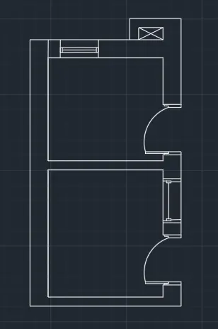
- Draw wash basin and toilet pan as per assumption.
- Fill the wall color using hatch from Autocad menu.
RESULT:-
FINAL SKETCH OF PART PLAN FOR THE TOILET AND UTILITIES ROOM.