Drafting of various geometries using Chamfer, Fillet tool in AutoCad
1)
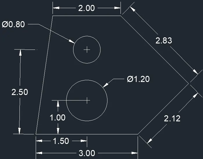
Note: In the above drawing 2 angles have not been mentioned they are, 135 degree between 3.00m and 2.12m lines and 90 degree between 2.12m and 2.83m lines.
Procedure:
- Open Auto cad and open new drawing.
- Type ‘LIMITS’ in command bar and set the sheet limit as per drawing.
- Type ‘UNITS’ in command bar and set the unit type as Decimal and unit in meter set precision as required for drawing.
- Now type ‘LINE’ in command bar and click anywhere in cad screen as a starting point for drawing.
- Keep ortho on so that the lines move only in Right angles.
- Let us start from base of the drawing. Draw the base dimension with given length in 0degree.
- Then draw the right hand side line with given angle 135 degree.
- Like this carry on the other lines.
- After the outer completion of drawing then we have to draw a circle inside.
- The dimension of centre point of circle is given using that make a centre point.
- The diameter of the circle is given.
- Type CIRCLE command and click on the centre point of circle.
- The types D on the command bars and input the given dia then press entre the required dia circle is obtained.
- Now the drawing part is done then do the required dimensioning.
- Do the dimensioning using linear method and adjust the text and arrow size as required.
2)
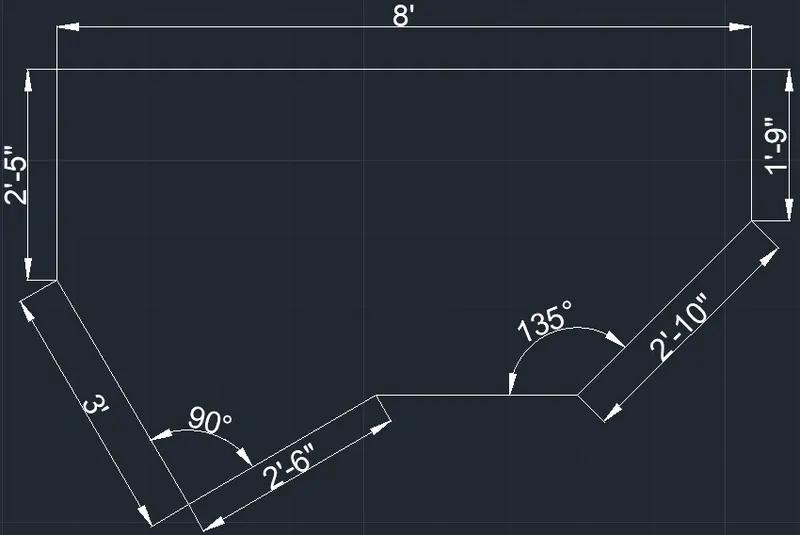
Procedure:
- Open Auto cad and open new drawing.
- Type ‘LIMITS’ in command bar and set the sheet limit as per drawing.
- Type ‘UNITS’ in command bar and set the unit type as Architectural and unit in inches required for drawing.
- Now type ‘LINE’ in command bar and click anywhere in cad screen as a starting point for drawing.
- Keep ortho on so that the lines move only in Right angles.
- Let us start from base of the drawing. Here the drawing is quite tricky to start the line to line internal angle is given as 90 degree, so first to know the outer angle subtract the inner angle by 180 degree. So we get the remaining as 90degree.
- Divide the angle so we get 45 degree, Draw a line with given length and apply the above angle.
- Now draw the left hand line as given internal angle and length.
- Then continue the drawing with given length and angle.
- This drawing is quite tricky because they have not given one angle so.
- So we have to use out some method so that we can get the correct angle.
- The last line length is not given so just type close in line command.
- Here the drawing part is done so start with the dimensioning work.
- Before starting go to Dimension style and there go to Primary units and there set as Architectural.
- Then while doing the dimensioning we can see that all the dimensions are in Architectural format.
- Then while doing the dimensioning we can see that the size of arrow and text may not match the drawing so do the required adjustments so that the dimension is clearly visible.
3)
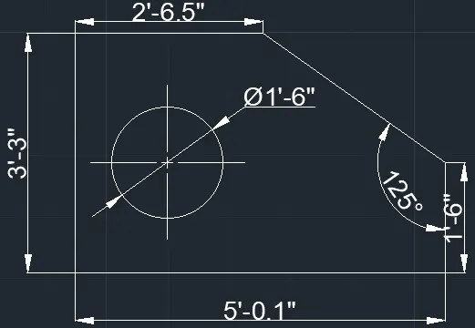
Procedure:
- Open Auto cad and open new drawing.
- Type ‘LIMITS’ in command bar and set the sheet limit as per drawing.
- Type ‘UNITS’ in command bar and set the unit type as Engineering and unit in inches required for drawing.
- Now type ‘LINE’ in command bar and click anywhere in cad screen as a starting point for drawing.
- Keep ortho on so that the lines move only in Right angles.
- Let us start from base of the drawing. As here the base is not that tricky so we can do it only by giving the input of given dimension.
- The all dimension are super clear only we have to be careful while typing the dimension.
- While typing the dimension we can see here the first one is in feet so we have to type a ' (single invited comma) to indicate it as feet.
- After completing all the drawing part start by doing the dimensioning part.
- Before starting go to Dimension style and there go to Primary units and there set as Engineering.
- Then while doing the dimensioning we can see that all the dimensions are in Engineering format.
- Then while doing the dimensioning we can see that the size of arrow and text may not match the drawing so do the required adjustments so that the dimension is clearly visible.
4)
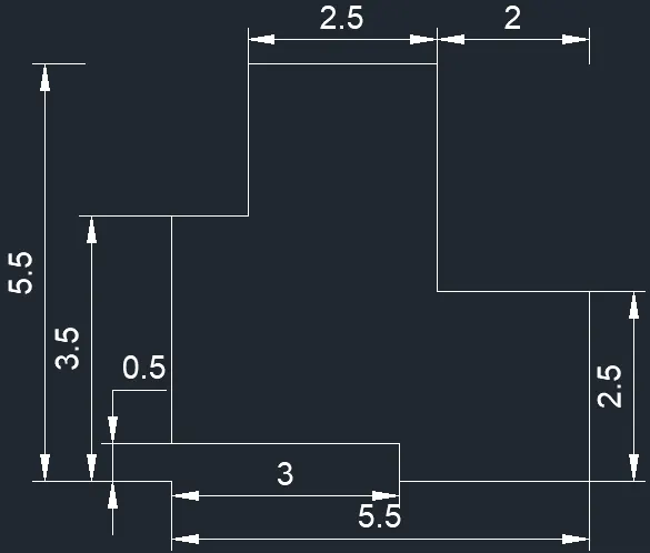
Procedure:
- Open Auto cad and open new drawing.
- Type ‘LIMITS’ in command bar and set the sheet limit as per drawing.
- Type ‘UNITS’ in command bar and set the unit type as Decimal and unit in meter set precision as required for drawing.
- Now type ‘LINE’ in command bar and click anywhere in cad screen as a starting point for drawing.
- Keep ortho on so that the lines move only in Right angles.
- Start from one corner of base. Input the length and angle.
- This is the simple drawing and all the details are given.
- After completing the drawing start with the dimensioning part.
- Do the dimensioning using linear method and adjust the text and arrow size so that it matches the drawing and clearly visible.
5)
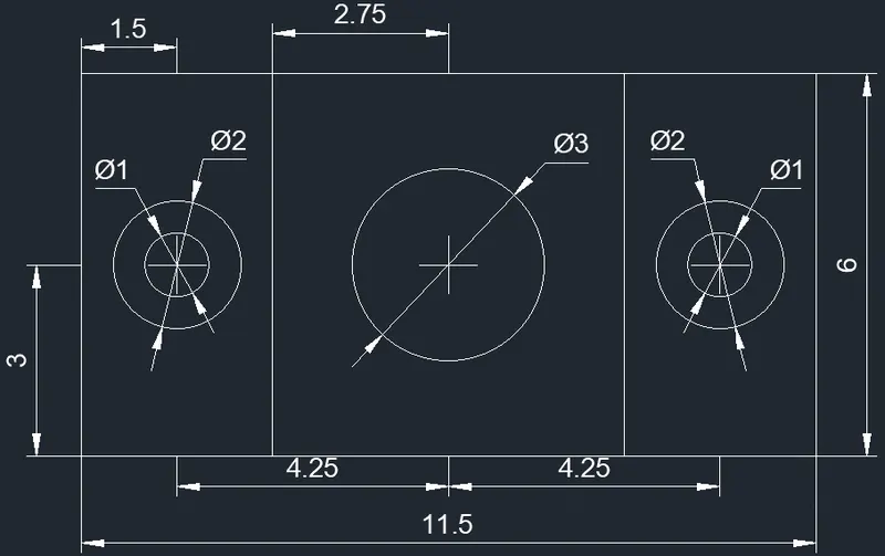
Procedure:
- Open Auto cad and open new drawing.
- Type ‘LIMITS’ in command bar and set the sheet limit as per drawing.
- Type ‘UNITS’ in command bar and set the unit type as Decimal and unit in meter set precision as required for drawing.
- Now type ‘LINE’ in command bar and click anywhere in cad screen as a starting point for drawing.
- Keep ortho on so that the lines move only in Right angles.
- Start from one corner of base. Input the length and angle.
- This is the simple drawing and all the details are given.
- After completing the outer diagram now start with the circles of which the diameter is given.
- The centre point placement reading is given using that mark the centre point.
- Using that centre point draw the circle using given radius and diameter.
- After completing the drawing start with the dimensioning part.
- Do the dimensioning using linear method and adjust the text and arrow size so that it matches the drawing and clearly visible.
6)
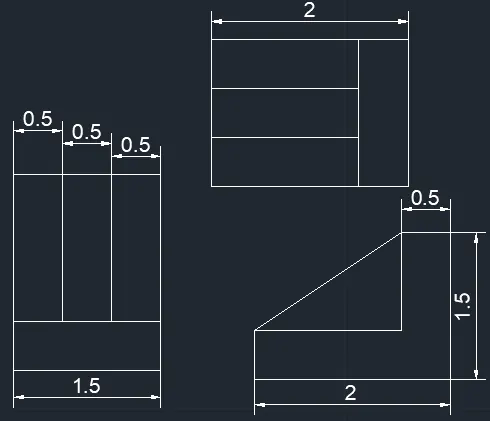
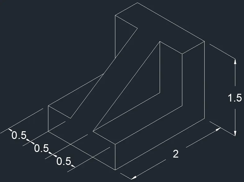
Procedure:
- Open Auto cad and open new drawing.
- Type ‘LIMITS’ in command bar and set the sheet limit as per drawing.
- Type ‘UNITS’ in command bar and set the unit type as meter and precision as required for drawing.
- Now type ‘LINE’ in command bar and click anywhere in cad screen as a starting point for drawing.
- Start doing the front view of the diagram in normal grid.
- After completing the front view change the view to isometric in snap grid setting.
- Change the isometric view to top level and draw the width as shown in figure.
- Next use copy command and select the first step and copy it for rest.
- Draw a diagonal line using the starting point and ending point of steps for waist slab.
- Give the thickness of the slab using copy command.
- Here the drawing part is complete and the remaining is dimensioning part.
- The extra lines are trimmed of using trim command.
- Do the dimensioning using linear method.
- After all the dimensioning part is done we can see that the dimensions are no aligned with the line or with isometric view.
- So go to annotation tab and select oblique command and select the dimension and give the required angle. Or
- Select the dimension to be edited and select the first point in the line for which dimension should be parallel and select the second point in the same.
- Repeat the same step for all the other dimensions.
7)
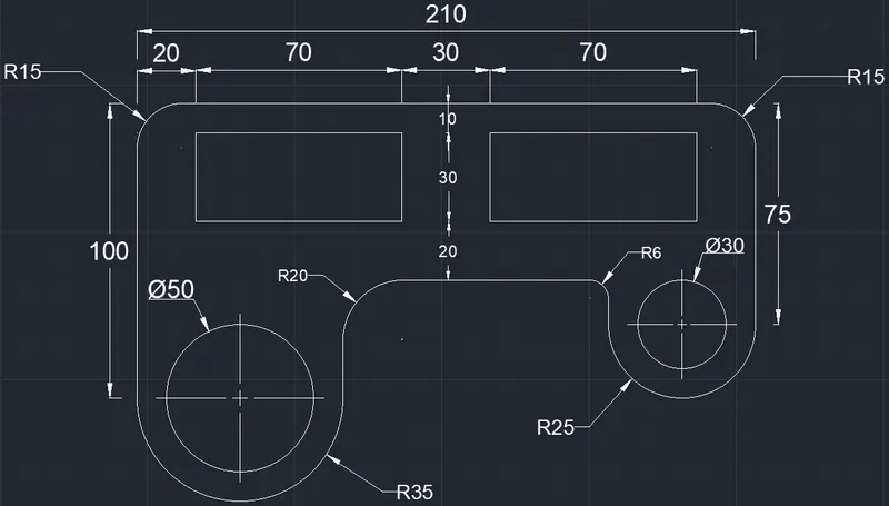
Procedure:
- Open Auto cad and open new drawing.
- Type ‘LIMITS’ in command bar and set the sheet limit as per drawing.
- Type ‘UNITS’ in command bar and set the unit type as Decimal and unit in meter set precision as required for drawing.
- Now type ‘LINE’ in command bar and click anywhere in cad screen as a starting point for drawing.
- Keep ortho on so that the lines move only in Right angles.
- Start from one corner of base. Input the length and angle.
- Here we have to use fillet command in some places.
- So first draw the line normally and use fillet command.
- Type fillet in command bar and put insert the given radius.
- Now select the one line of the corner and next the other corner then we can see the corner has been changed from sharp edge to curvy one.
- Here we have also to use the arc command in 2 places.
- After all the line work is completed then go with the Fillet one after that we have to go with the arc.
- The radius of the arc and diameter of the circle is given so by that we can easily find out the centre point readings.
- After knowing the centre point readings mark it and select the line arc command.
- Here select Start, Centre and End, click on the start point and centre point and then next the ending point.
- So by the above method we have to do the remaining arcs.
- Next go with the circle and select the centre point and type D in the command box and input the diameter given.
- By the above steps we can complete the given drawing.
- Do the dimensioning using linear method and adjust the text and arrow size so that it matches the drawing and clearly visible.
8)
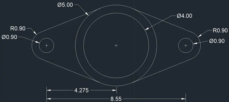
Procedure:
- Open Auto cad and open new drawing.
- Type ‘LIMITS’ in command bar and set the sheet limit as per drawing.
- Type ‘UNITS’ in command bar and set the unit type as Decimal and unit in meter set precision as required for drawing.
- Keep ortho on so that the lines move only in Right angles.
- Select the circle command and make a centre point anywhere in the screen.
- The diameter is given so select diameter in circle command and input the value.
- The required circle is obtained, draw the second circle and the centre part is done.
- Now draw a line in the centre point because the c/c distance is given of the right and left hand side ones.
- Use offset for that and do the circle using the circle command.
- Then the arc is given so do the arc using the same centre point or do the circle with the given radius.
- Now select the line command and join the tangent point of centre circle and beside one.
- Keep the tangent point on so that the tangent point can easily obtain.
- After drawing the lines now trim off all the excess lines and the drawing is completed.
- Do the dimensioning using linear method and adjust the text and arrow size so that it matches the drawing and clearly visible.
9)
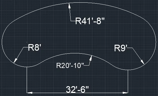
Procedure:
- Open Auto cad and open new drawing.
- Type ‘LIMITS’ in command bar and set the sheet limit as per drawing.
- Type ‘UNITS’ in command bar and set the unit type as Architectural and unit in inches required for drawing.
- Keep ortho on so that the lines move only in Right angles.
- Select the circle command and make a centre point anywhere in the screen.
- The radius is given so input the radius of the circle in command bar.
- The required circle is obtained. The centre point spacing is given offset the centre point of the other circle and draw the circle by same method.
- Now draw 2 circles above and below the previous circles using Tan, Tan, and Radius.
- After that trim off the all extra lines, by this the drawing is completed.
- Before starting go to Dimension style and there go to Primary units and there set as Architectural.
- While doing the dimensioning we can see that all the dimensions are in Architectural format.
- Then while doing the dimensioning we can see that the size of arrow and text may not match the drawing so do the required adjustments so that the dimension is clearly visible.
10)
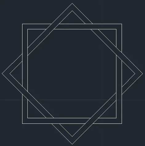
Procedure:
- Open Auto cad and open new drawing.
- Type ‘LIMITS’ in command bar and set the sheet limit as per drawing.
- Type ‘UNITS’ in command bar and set the unit type as Decimal and unit in meter set precision as required for drawing.
- Keep ortho on so that the lines move only in Right angles.
- Select the Rectangular command and specify a point in the screen.
- Select dimension in the command option and input the random dimension.
- After that use offset command to obtain the thickness.
- Select the present drawing and select rotation command.
- Select the base point and select copy the drawing will be copied and rotated.
- Type the angle required and trims off the lines to get the above diagram.
11)
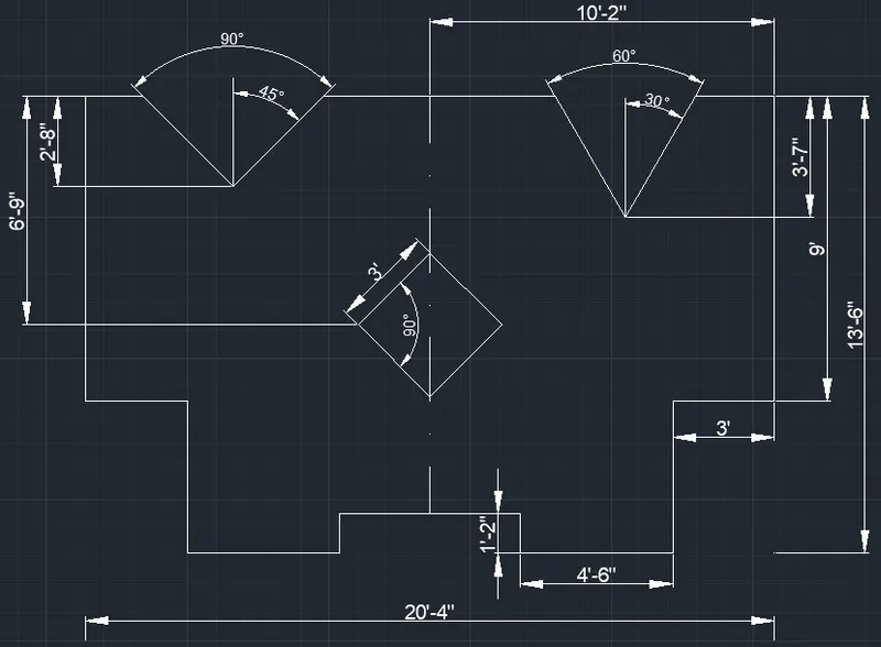
Procedure:
- Open Auto cad and open new drawing.
- Type ‘LIMITS’ in command bar and set the sheet limit as per drawing.
- Type ‘UNITS’ in command bar and set the unit type as Architectural and unit in inches required for drawing.
- Now type ‘LINE’ in command bar and click anywhere in cad screen as a starting point for drawing.
- Keep ortho on so that the lines move only in Right angles.
- Start from one corner of base. Input the length and angle.
- While inserting the dimension beware to put single invited comma, Using this complete the drawing.
- After completing the basic now we have to do all the extra work like inside box and all the shapes.
- After completing the drawing now do the dimensioning work.
- Before starting go to Dimnesion style and there go to Primary units and there set as Architectural.
- Then while doing the dimensioning we can see that all the dimnesions are in Architectural format.
- Then while doing the dimnesioning we can see that the size of arow and text maynot match the drawing so do the required adjustments so that the dimension is clearly visible.