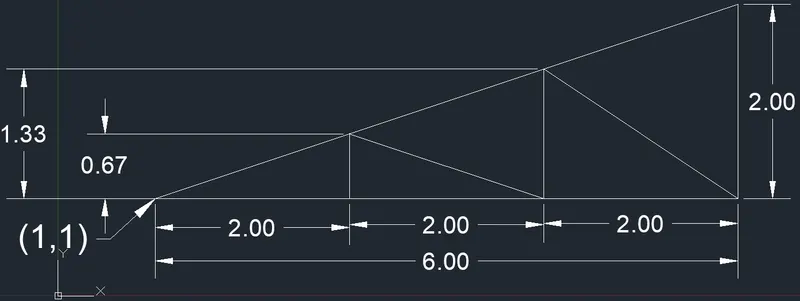
Creation of geometries by Coordinate system methods using AutoCad
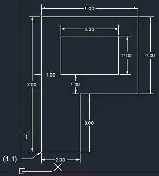
Aim: Create the geometries from P1 to P2 using all the coordinates system methods.
P1)
This drawing is done using Absolute co-ordinate system
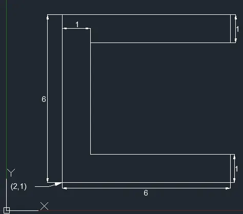
The procedure of this drawing as follow:
- Open Auto cad and open new drawing.
- Type ‘LIMITS’ in command bar and set the sheet limit as per drawing.
- Type ‘UNITS’ in command bar and set the unit type and precision as required for drawing.
- Now type ‘LINE’ in command bar and type the co-ordinate (2, 1).
- Type (8, 1) for the second point as specified in drawing.
- Type (8, 2) for the third point as specified in drawing.
- Type (3, 2) for the forth point as specified in drawing.
- Type (3, 6) for the fifth point as specified in drawing.
- Type (8, 6) for the sixth point as specified in drawing.
- Type (8, 7) for the seventh point as specified in drawing.
- Type (2, 7) for the eighth point as specified in drawing.
- Type CLOSE in command bar and the lines meets the start point.
- The drawing is completed by above method.
P2)
This drawing is done using Relative co-ordinate system
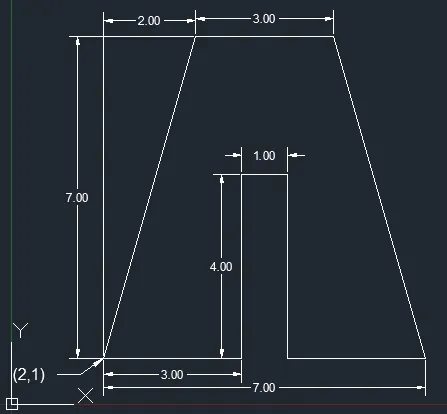
The procedure of this drawing as follow:
- Open Auto cad and open new drawing.
- Type ‘LIMITS’ in command bar and set the sheet limit as per drawing.
- Type ‘UNITS’ in command bar and set the unit type and precision as required for drawing.
- Now type ‘LINE’ in command bar and type the co-ordinate (2, 1).
- Type @ (3, 0) for the second point as specified in drawing.
- Type @ (0, 4) for the third point as specified in drawing.
- Type @ (1, 0) for the forth point as specified in drawing.
- Type @ (0, -4) for the fifth point as specified in drawing.
- Type @ (3, 0) for the sixth point as specified in drawing.
- Type @ (-2, 7) for the seventh point as specified in drawing.
- Type @ (3, 0) for the eighth point as specified in drawing.
- Type CLOSE in command bar and the lines meets the start point.
- The drawing is completed by above method.
P4)
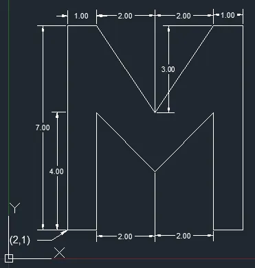
P5)
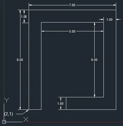
P7)
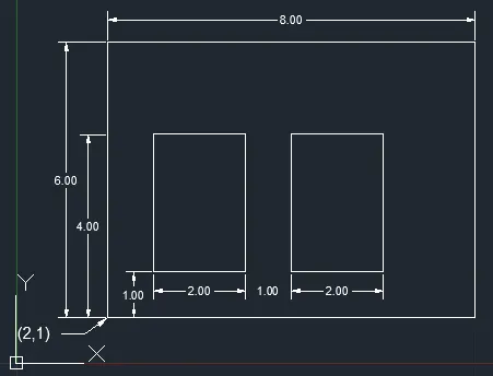
P8)
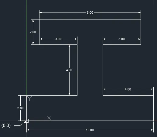
P9)
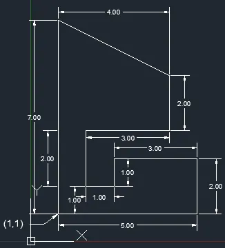
P10)
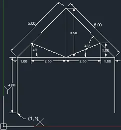
The drawings of profile and trusses using any coordinate system methods.
The below drawings are done by Relative Co-ordinate system
1)
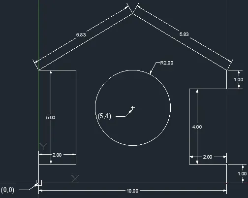
The procedure of this drawing as follow:
- Open Auto cad and open new drawing.
- Type ‘LIMITS’ in command bar and set the sheet limit as per drawing.
- Type ‘UNITS’ in command bar and set the unit type and precision as required for drawing.
- The below steps are of Relative coordinate system.
- Now type ‘LINE’ in command bar and type the co-ordinate (0, 0) take this as first point.
- Type @ (10, 0) for the second point as specified in drawing.
- Type @ (0, 1) for the third point as specified in drawing.
- Type @ (-2, 0) for the forth point as specified in drawing.
- Type @ (0, 4) for the fifth point as specified in drawing.
- Type @ (2, 0) for the sixth point as specified in drawing.
- Type @ (0, 1) for the seventh point as specified in drawing.
- Type @ (-5, 3) for the eighth point as specified in drawing.
- Type @ (-5, -3) for the ninth point as specified in drawing.
- Type @ (2, 0) for the tenth point as specified in drawing.
- Type @ (0, -5) for the eleventh point as specified in drawing.
- Type @ (-2, 0) for the twelfth point as specified in drawing.
- Type CLOSE in command bar and the lines meets the start point.
To draw the circle:
- Select line command and type coordinate (5, 4) we will get centre point of circle.
- Select circle from draw box
- Select radius and type 2.00 then we have the circle.
2)
3)