Creating a Floor plan, Footing detail and Isometric view using AutoCad
C1) Cross section of Load bearing wall over spread footing
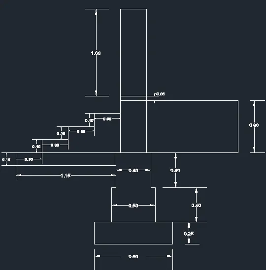
Procedure:
- Open Auto cad and open new drawing.
- Type ‘LIMITS’ in command bar and set the sheet limit as per drawing.
- Type ‘UNITS’ in command bar and set the unit type as meter and precision as required for drawing.
- Now type ‘LINE’ in command bar and click anywhere in cad screen as a starting point for drawing.
- Take the cross hair to right and apply the value 0.9 the line will appear.
- While doing in these methods keep Ortho on for accurate angles.
- Now select Offset command and take offset of 0.4m thicknesses.
- Select Offset command and take offset of 0.15m in either side from the base line.
- Take offset of 0.4m as height of next step.
- Now trim off the extra lines and make ready for next step offset.
- Do the same for the other remaining footings.
- Now after footing make the wall take offset of 50mm from both side of last footing.
- The height of wall is given so draw a line of that height 1.65m.
- Draw the horizontal line of 1m in the starting point of wall.
- Take offset of 0.6m as shown if diagram.
- Now start doing the steps. Start the step from the given dimension and draw line using line command and given dimension vertically and horizontally.
- Now the diagram is completed the remaining part is dimensioning.
- Do the dimensioning using linear method and adjust the text and arrow size as required.
C2) Cross section of Isolated footing
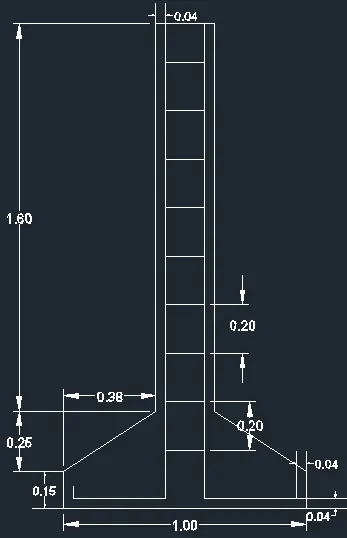
Procedure:
- Open Auto cad and open new drawing.
- Type ‘LIMITS’ in command bar and set the sheet limit as per drawing.
- Type ‘UNITS’ in command bar and set the unit type as meter and precision as required for drawing.
- Now type ‘LINE’ in command bar and click anywhere in cad screen as a starting point for drawing.
- Take the cross hair to right and apply the value 1.0m the line will appear we are starting from base of the footing.
- The height is of 0.15m so take the cross hair vertically and type the value and press entre.
- The footing is sloped one the value is given in the form of right angled triangle, So take the width and height of the triangle and make the slope as given.
- The height of column is given so draw the line by taking cross hair vertically and put the value.
- The half side/ one side of drawing are completed so use mirror command.
- Select the one side of drawing and mirror it.
- The reinforcement part is started by doing offset of given column cover.
- The stirrups spacing is given. This is done using array command.
- Select the object that should be arrayed and select the path then insert the c/c distance as given.
- Now the diagram is completed the remaining part is dimensioning.
- Do the dimensioning using linear method and adjust the text and arrow size as required.
C3) Line diagram of a two Bedroom building.
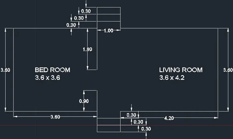
Procedure:
- Open Auto cad and open new drawing.
- Type ‘LIMITS’ in command bar and set the sheet limit as per drawing.
- Type ‘UNITS’ in command bar and set the unit type as meter and precision as required for drawing.
- Now type ‘LINE’ in command bar and click anywhere in cad screen as a starting point for drawing.
- Enter the given room dimension w.r.t length and width of room.
- Trim out the line where the openings are provided.
- Draw the top view of step as per drawing and mirror it for the other side.
- Now we have to name the room select the text comment from annotation bar.
- Write down the names of room as shown in figure.
- Edit the text size so that it is clearly visible.
- Now the diagram is completed the remaining part is dimensioning.
- Do the dimensioning using linear method and adjust the text and arrow size as required.
C4) Cross section of Load bearing wall showing foundation details.
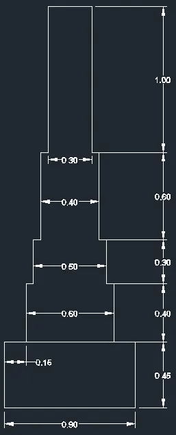
Procedure: Here the same procedure is used as in C1 only the dimensions are changed w.r.t drawing.
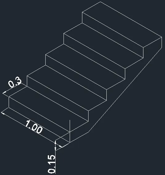
C5) Isometric view of steps
Procedure:
- Open Auto cad and open new drawing.
- Type ‘LIMITS’ in command bar and set the sheet limit as per drawing.
- Type ‘UNITS’ in command bar and set the unit type as meter and precision as required for drawing.
- Now type ‘LINE’ in command bar and click anywhere in cad screen as a starting point for drawing.
- Start doing the front view of the diagram in normal grid.
- After completing the front view change the view to isometric in snap grid setting.
- Change the isometric view to top level and do the width of the staircase of 1m as shown in figure.
- Next use copy command and select the first step and copy it for rest.
- Draw a diagonal line using the starting point and ending point of steps for waist slab.
- Give the thickness of the slab using copy command.
- Here the drawing part is complete and the remaining is dimensioning part.
- The extra lines are trimmed of using trim command.
- Do the dimensioning using linear method.
- After all the dimensioning part is done we can see that the dimensions are no aligned with the line or with isometric view.
- So go to annotation tab and select oblique command and select the dimension and give the required angle. Or
- Select the dimension to be edited and select the first point in the line for which dimension should be parallel and select the second point in the same.
- Repeat the same step for all the other dimensions.
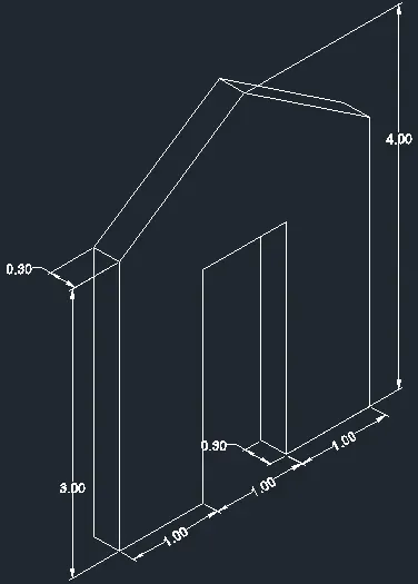
C6) Isometric view of Gable wall
Procedure:
- Open Auto cad and open new drawing.
- Type ‘LIMITS’ in command bar and set the sheet limit as per drawing.
- Type ‘UNITS’ in command bar and set the unit type as meter and precision as required for drawing.
- Now type ‘LINE’ in command bar and click anywhere in cad screen as a starting point for drawing.
- Start doing the front view of the diagram in normal grid.
- After completing the front view change the view to isometric in snap grid setting.
- Change the isometric view to left or right side grid and start to do the thickness of Gable wall using copy command.
- Next use copy command and to show the thickness of Gable wall.
- In isometric offset command cannot be used.
- After doing all the thickness of wall then trim the extra and unwanted lines.
- Here the drawing part is complete and the remaining is dimensioning part.
- The extra lines are trimmed of using trim command.
- Do the dimensioning using linear method.
- After all the dimensioning part is done we can see that the dimensions are no aligned with the line or with isometric view.
- So go to annotation tab and select oblique command and select the dimension and give the required angle. Or
- Select the dimension to be edited and select the first point in the line for which dimension should be parallel and select the second point in the same.
- Repeat the same step for all the other dimensions.