Creating a Residence Layout, Seating plan, Toilet and Utility room plan using AutoCad
1Q]
AIM: -
Sketch the layout of a Residence using AutoCAD Tools and Layers Option
PROCEDURE: -
Set the units to Engineering using UNITS command
Set the lower limit and upper limit of the screen using LIMITS command
Lower limit: 0’,0’
Upper limit: 100’,100’
Choose the Construction line command
Draw a vertical line and horizontal line. The two lines intersects and this point is the starting point.
Start from left and go to right.
Select the OFFSET command with offset distance 9” for External wall thickness
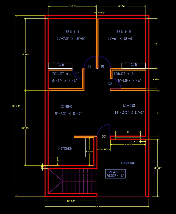
Using OFFSET command draw staircase room of size 12’6” * 6’
By using TRIM command, trim the unnecessary lines
Draw staircase with size of Tread- 1’ and Riser- 6”
Draw Kitchen Room of size 12’-6” * 6’-8” above the staircase.
Inside the Kitchen draw the slab of thickness 2’-0” units.
Draw the internal wall of thickness -4.5”.
Above the Kitchen, draw Living room of size 8’-7.5” * 11’-0” with wall thickness
Use FILLET command and TRIM command to draw wall thickness
On above the Dining, draw Toilet # 1 with size: 8’-3” *4’-6”
Draw Bed Room # 1 of size 11’-7.5” * 12’-0”
Beside Bed Room # 1, draw Bed Room # 2 of size: 11’-6” * 12’-0”
Below the Bed Room # 2 draw Toilet # 2 of size: 8’-1.5” * 4’-6”
Below the Toilet # 2, draw Living Room of size: 14’-10.5” * 11’-0”
At the end provide Parking of size: 11’-9” * 13’-9.5”
Provide Door (D3) at Entrance of Living Room with size: 3’-3” * 6’-8”
Beside the Door (D1) draw the Window with length of 6’-0” units
Draw Doors (D2) size: 2’-6” * 6’-8” to both Toilets
Draw Doors (D1) size: 3’-0” * 6’-8” to both Bed rooms.
TRIM the all unnecessary lines and show the external wall thickness as 9” and internal wall thickness as 4.5”
Select LAYER properties dialogue box
Create New Layers for
Doors, Dimensions, External Walls, Internal Walls, Gate, Labels, Railings, Stairs and Windows.
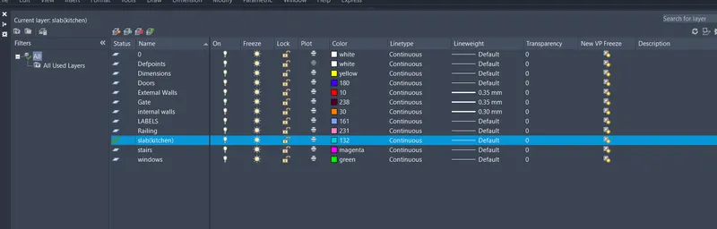
Select different colour to each layer created.
Set the Dimensions as Current Layer
Provide Dimensions to each Room and wall thickness
Set External walls as current layer and select all External walls
All the External wall colour changes to Layer colour
Set Internal walls as current layer and select all Internal walls
Set Doors as current layer and select the all Door Types D1, D2, D3
Set Windows as current layer and select all the provided windows
Set Stairs as current layer and select the Stairs.
Change the line type to half of the stairs as per the drawing.
Set Labels as current layer and write all the Labels under Labels layer.
Change the Line weight of Internal walls to 0.3mm and External walls to 0.35mm
RESULT: -
2Q]
AIM: -
Sketch the Seating Plan for an Outdoor Canopy using AutoCAD
PROCEDURE: -
Select Line command
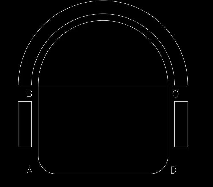
draw RECTANGLE ABCD with dimensions 295 * 201 mm
At the top side BC of the Rectangle draw ARC using Start End Angle option
Start as B point, End as C point and angle 180 degrees
Select OFFSET command
Specify offset distance as 15mm units and select object as ARC
Place the offset line above the ARC
Select offset command with offset distance of 30mm place one more Arc above this.
Select the Line tool and close the two Arcs at the ends.
Using RECTANGLE command draw Rectangle of size 30mm * 100 mm exactly below the ARCS
Select the MIRROR command
Select the object: Rectangle 30 * 100 mm
Mirror line: Midpoint of line AD and BC
Don’t erase the source object.
Select FILLET command with radius 40mm
Use the Fillet tool at points A and D
Chair is Ready
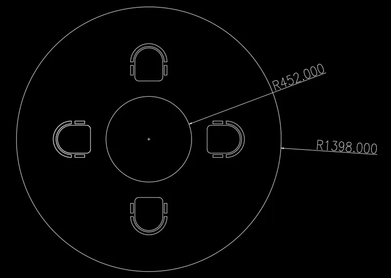
Select CIRCLE command and draw Circle using centre and Radius of 1398mm units
Select CIRCLE command and draw Circle using centre as previous circle and Radius of 452mm units
Both circles are concentric circles.
Move the chair to Smaller circle and place at appropriate position.
Select the ROTATE command
Specify the base point as centre of circle
Using the copy option in ROTATE Command, rotate the chair to 90 degrees, 270 degrees and 180 degrees.
Outside canopy with Seating is ready
RESULT: -
3Q]
AIM: -
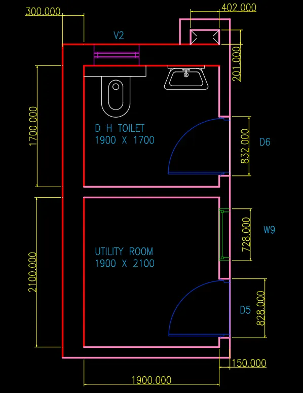
Sketch the part plan of Toilet and Utility Room with thickness of outer walls as 300mm and internal walls as 150mm.Use layers
PROCEDURE: -
Choose the Construction line command
Draw a vertical line and horizontal line. The two lines intersects and this point is the starting point.
Start from left and go to right.
Select the OFFSET command with offset distance 300mm for External wall thickness
Draw internal wall of thickness 150mm using OFFSET command
Draw the Utility Room of sizes 1900mm length and 2100mm width
Above the Utility Room, draw Toilet Room of sizes 1700 * 1900mm
Use OFFSET, TRIM, FILLET commands to draw wall thickness
Draw ventilator of width 631mm in Toilet room
Draw Door (D6) having width of 832mm to Toilet
Draw Door (D5) having width of 828mm to Utility room
Draw window (W9) having width of 728mm to utility rom
Open Layers dialogue box
Add layers
Inter wall, External wall, Dimensions, Labels, Window, Ventilator, Doors
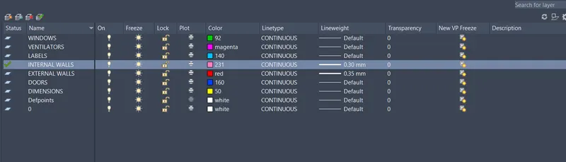
Select different colour to each layer created.
Set the Dimensions as Current Layer
Provide Dimensions to each Room, window, door, ventilator and wall thickness
Set External walls as current layer and select all External walls
All the External wall colour changes to Layer colour
Set Internal walls as current layer and select all Internal walls
Set Doors as current layer and select the all Door Types D5, D6
Set Windows as current layer and select all the provided windows
Set Labels as current layer and write all the Labels under Labels layer.
Set ventilator as current layer and select the ventilator under ventilator layer.
Change the Line weight of Internal walls to 0.3mm and External walls to 0.35mm
RESULT: -