Drafting of various geometries using Chamfer, Fillet tool in AutoCad
Question -3 Engineering Drawing:-
1. The drawing was executed on engieering mearsurement.
2. All dimension are in inches.
Detailed Procedure:-
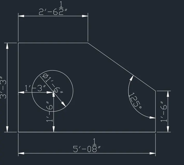
1. Rectangle of dimension 5'- 0.1" * 3'-3" is constructed.
2. Chamfering option for two dimensions 2'-9" * 2'-5.6" is used.
3. Circle of diameter 1'-6" is constructed.
4. the circle created is moved to the designated distance at the offset of 1'-3" x-axis & 1'-6" y axis.
5. Dimension are recorded accordingly in the sketch.
Result:-
a. The result is shown in the screen shot as attached below.
Q-4
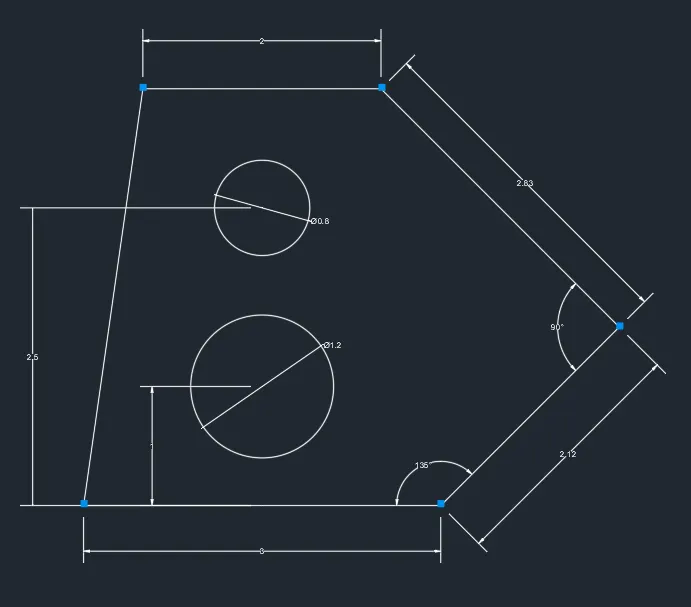
1. The drawing was executed on decimal scale
2. All dimension are in millimeter
Detailed Procedure:-
1. Lines of diemsion as mentioned in the drawings were created
Result:-
a. The result is shown in the screen shot as attached below.
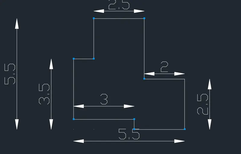
Question - Slide 5
1. The drawing was executed on decimal scale.
2. All dimension are in millimeter.
Detailed Procedure:-
1. Rectangle of dimension 11.5*6 was created. Ciricle of dia 3 mtrs was created. Line of infinite length was creatd with XL command, offset of 2.75 from cicile centre on both sides were created. From this point, 2 circles at distance 1.5 from the lines were created with centre point at dia of circle 1,2.
Result:-
a. The result is shown in the screen shot as attached below.
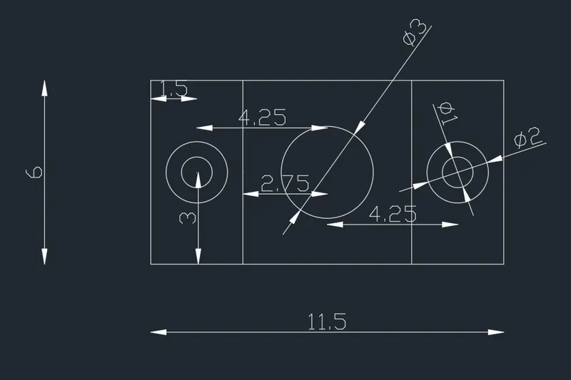
Question - 1c
1. The drawing was executed on decimal scale.
2. All dimension are in millimeter.
Detailed Procedure:-
1. Three rectangles as shown below were created, chamfer tool was used in one rectangle. WIth the application of line command L lines were created at the interval of 0.5. The final result is attached below for the reference.
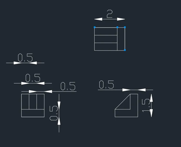
1. The drawing was executed on decimal scale.
2. All dimension are in millimeter.
Detailed Procedure:-
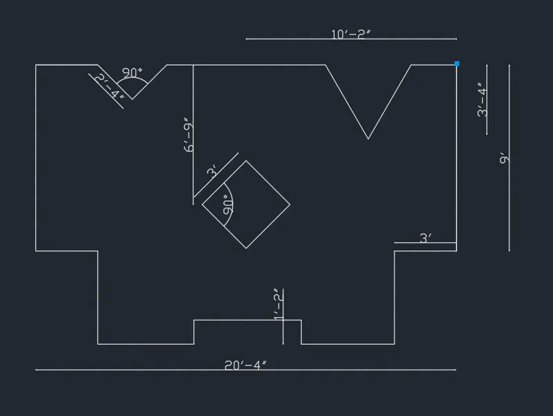
1. As attached below, the sketch is drawn and attached below for reference.
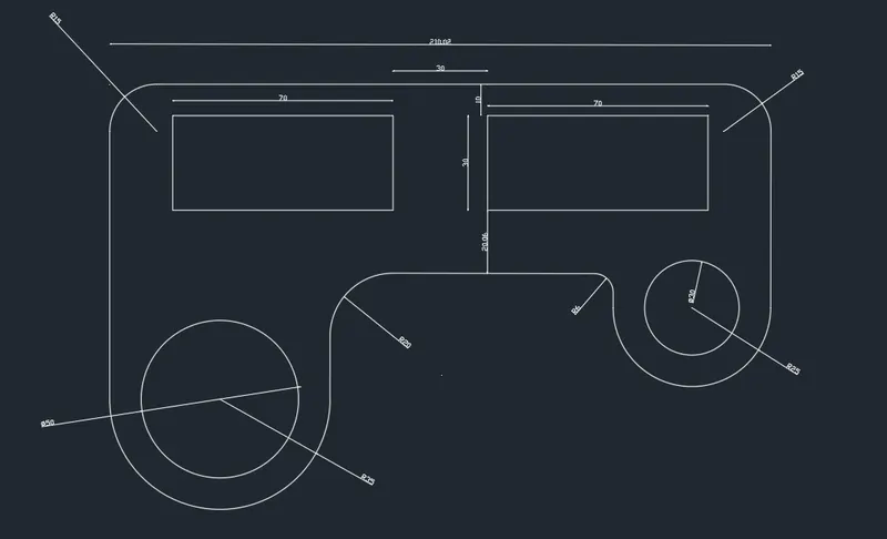
1. The drawing was executed on decimal scale.
2. All dimension are in millimeter.
Detailed Procedure:-
1. As attached below, the sketch is drawn and attached below for reference.
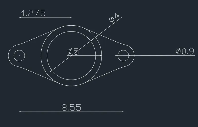
Second last Question:-
1. The drawing was executed on decimal scale.
2. All dimension are in millimeter.
Detailed Procedure:-
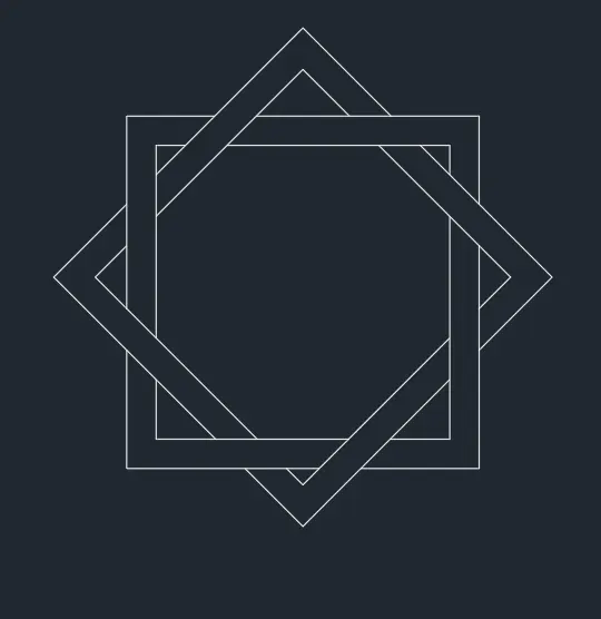
1. One rectangle of dimension 10*10 is created, with offset of 1 was made. The two rectangles were copied, and the rectangles were rotated by 45 degree. Then the, rectangles were trimmed as per the requirement, for the shown diagram.
Result:-
1. The final result obtained is shown below.