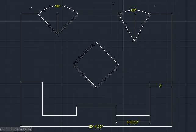
Drafting of various geometries using Chamfer, Fillet tool in AutoCad
Aim:-
The tutorial will expain step by step procedure of sketching and editing tools from below diagrams and to create in autocad.
Introducation:
Setting the standard: in the following topics
We will learn about the standard setting used in autocad before starting the drafting process.
Units types are decimal,architectural,engineering, fractional and scienticfic.
Procedure:-
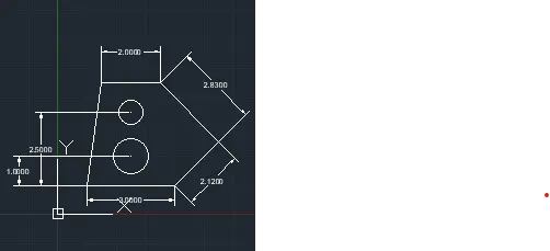
C1:-
set the units to decimal,and milimeter,then press the enter
then, type l command to command box , and enter
- specify first point 1,1 and press enter
- specify next point ;at @3.00<0
- specify next point ;at @2.12<45
- specify next point ;at @2.83<135
- specify next point ;at @2.00<180
- specify next point close or undo;close press enter
- Then type circle in command box,
- pick the point 1.50,1.00
- click thr circle command to centre,diameter
- then draw the circle in 1.00 point diameter 1.20
- then again draw the circle in 2.50 point in diamter 0.80
- Creat the diamension pick the points of the line
- Enter the dimin command the command box
- Then, create the next angular diamension to the below diagram:
Result:-
C2:-
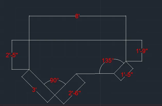
set the units to Architectural and inch,then press the enter
then, type l command to command box , and enter
- specify first point 1,1 and press enter
- specify next point ;at @2'6"<135
- specify next point ;at @3'<0
- specify next point ;at @2'10"<45
- specify next point ;at @1'9"<90
- specify next point ;at @8'<180
- specify next point ;at @2'5"<270
- specify next point close or undo;close press enter
- Creat the diamension pick the points of the line
- Enter the dimin command the command box
- Then, create the next angular diamension to the below diagram:
Result:-
C3. )
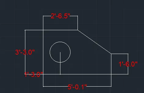
set the units to engineering and inch,then press the enter
then, type l command to command box , and enter
- specify first point 1,1 and press enter
- specify next point ;at @5'0.5"<0
- specify next point ;at @1'6"<90
- specify next point ;at @3'0.6"<135
- specify next point ;at @2'6.5"<180
- specify next point ;at @3'3"<270
- specify next point close or undo;close press enter
- Then type circle command and enter , pick the point 1'6" diameter at 1'6"
- Creat the diamension pick the points of the line
- Enter the dimin command the command box
- Then, create the next angular diamension to the below diagram:
result:
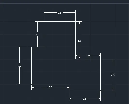
c.4).
set the units to decimal and milimeter then press the enter
then, type l command to command box , and enter
- specify first point 1,1 and press enter
- specify next point ;at @3<0
- specify next point ;at @0.50<270
- specify next point ;at @2.50<0
- specify next point ;at @2.50<90
- specify next point ;at @2.00<180
- specify next point ;at @3.00<90
- specify next point ;at @2.50<180
- specify next point ;at @2.00<270
- specify next point ;at @1.00<180
- specify next point close or undo;close press enter
- Creat the diamension pick the points of the line
- Enter the dimin command the command box
- Then, create the next angular diamension to the below diagram:
c.5).
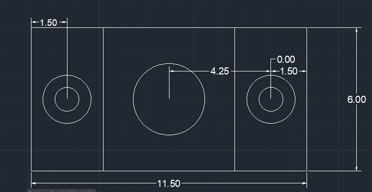
set the units to decimal and milimeter then press the enter
then, type l command to command box , and enter
- specify first point 1,1 and press enter
- specify next point ;at @11.5<0
- specify next point ;at @6<90
- specify next point ;at @11.5<180
- specify next point ;at @6<270
- specify next point 1.11.5 and press enter
- specify next point into mid point of the the line 11.5 and press enter
- specify next point ;at @6<270
- then offset the line theough 2.75 left nad right and press enter
- pick the centre point of the left side portion and type circle command and
- specify the point diameter 2.00 and press enter
- specify the point diameter 1.00 and press enter
- specify next point close or undo;close press enter
- Creat the diamension pick the points of the line
- Enter the dimin command the command box
- Then, create the next angular diamension to the below diagram:
c.6).
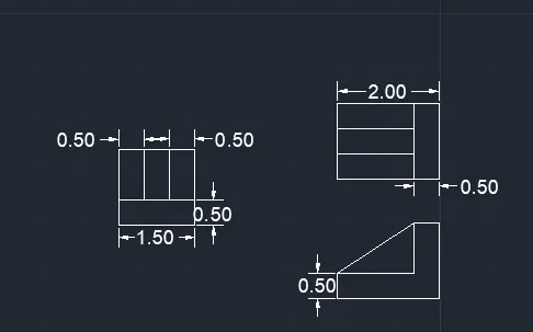
set the units to decimal and milimeter then press the enter
then, type l command to command box , and enter
1.
- specify first point 1,1 and press enter
- specify next point ;at @1.5<0
- specify next point ;at @1.5<90
- specify next point ;at @1.50<270
- then , offset line through 0.5 into 2 lines
- offset again the line to the bottom line through 0.5
2. type line command and press enter
- specify next point ;at @2.00<0
- specify next point ;at @1.5<90
- specify next point ;at @2<180
- specify next point ;at @1.5<270
- and offset line above line through 0.5 into two times
3. type line command and press enter
- specify next point ;at @2.00<0
- specify next point ;at @1.5<90
- specify next point ;at @0.5<180
- specify next point ;at @1.0<270
- specify next point ;at @1.5<180
- specify next point ;at @2.5<30
- And then trim the line select it and enter it.
- specify next point close or undo;close press enter
- Creat the diamension pick the points of the line
- Enter the dimin command the command box
- Then, create the next angular diamension to the below diagram:
c.7).
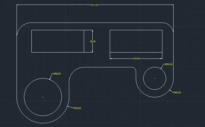
set the units to decimal and milimeter then press the enter
then, type l command to command box , and enter
- specify first point 1,1 and press enter
- specify next point ;at @100<90
- specify next point ;at @210<0
- specify next point ;at @75<270
- type the circle command and pick the point 75<270 end point of it
- then, click the centre,radius of the circle R25 and press enter
- Again the centre of the cicle dia 30 and click circle command
- Then, Again pick te point 100 to draw the circle and click circle command in centre, radius through r35 and press entre
- And again pick the centre of the circle to draw the circle of diameter at dia 50 in it. then trim the circle of radius .
- Then pick the rectangle and value 30,70 and press entre
- Then type fillet in command box,
- Then , pick the select point of fillet and give the value of the fillets.
- give the value of radius of the fillet,R6 and press entre
- specify next point close or undo;close press enter
- Creat the diamension pick the points of the line
- Enter the dimin command the command box
- Then, create the next angular diamension to the below diagram:
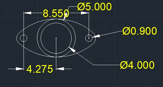
C.8).
set the units to decimal and milimeter then press the enter
then, type l command to command box , and enter
- specify first point 1,1 and press enter
- specify next point centre , diameter @4 and press enter
- specify next point centre , diameter @5 and press entre
- specify next point centre , diameter @0.90 and press entre
- specify next point centre , radius @0.90 and press entre
- specify next point centre , diameter @0.90 and press entre
- specify next point centre , radius @0.90 and press entre
- then, the join the circle with link like a tangent.
- specify next point close or undo;close press enter
- Creat the diamension pick the points of the line
- Enter the dimin command the command box
- Then, create the next angular diamension to the below diagram:
C. 9).
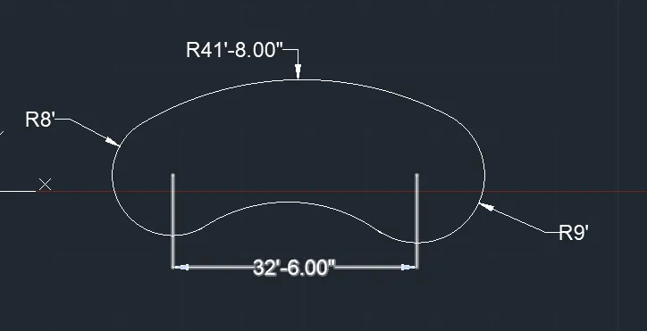
set the units to engineering and inch then press the enter
then, type l command to command box , and enter
- specify first point 1,1 and press enter
- specify next point ;at @32'6"<0
- specify next point to the centre , radius R8' and press entre
- specify next point to the centre,radius R9' and press entre
- in the distance of 32'6" centre of the circle and press entre
- specify next point to the centre, radius R41'6" and press entre
- specify next point to the centre,radius R20'10" and press entre
- specify next point close or undo;close press enter
- Creat the diamension pick the points of the line
- Enter the dimin command the command box
- Then, create the next angular diamension to the below diagram:
C.10.)
set the units of decimal and milimeter then press the enter
then, type l command to command box , and enter
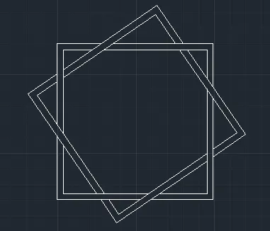
- specify next point enter rec command @5,5
- Again specify next point rec command @5,5
- then enter move command and select one square and move to next square .
- And then trim the line select it and enter it.
- specify next point close or undo;close press enter
- Creat the diamension pick the points of the line
- Enter the dimin command the command box
- Then, create the next angular diamension to the below diagram:
C.11.)
set the units to engineering and inch then press the enter
then, type l command to command box , and enter
- specify first point 1,1 and press enter
- specify next point ;at @4'6"<0
- specify next point ;at @1'2"<90
- specify next point ;at @4'<90
- specify next point ;at @9'<90
- specify next point ;at @3'<0
- specify next point ;at @2'8"<315
- specify next point ;at @2'8"<90
- specify next point ;at @3'6"<0
- Then, mirror the object and click and select that
- to wherever u want it.
- type polycon in command box and pick base point
- select value of polycon and select inscribed circle and press entre
- to creat the polycon
- specify next point close or undo;close press enter
- Creat the diamension pick the points of the line
- Enter the dimin command the command box
- Then, create the next angular diamension to the below diagram: