Creating a Floor plan, Footing detail and Isometric view using AutoCad
Aim:-
To creat the model c1 to c6 in autocad software and wrote the procedure in report format shown as a given below:
Procedure:-
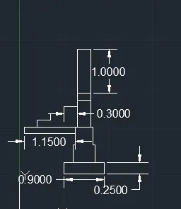
C1:-c.s of load bearing wall over spread footing.
solve the model in polar coordinate system;
set the units to decimal,and milimeter,then press the enter
then, type l command to command box , and enter
- specify first point 1,1 and press enter
- specify next point ;at @0.90<0
- specify next point ;at @0.25<90
- specify next point ;at @0.10<180
- specify next point ;at @0.50<180
- specify next point ;at @0.10<180
- specify next point ;at @0.25<270
- specify next point ;at @0.40<90
- specify next point ;at @0.05<0
- specify next point ;at @0.40<90
- specify next point ;at @0.25<90
- specify next point ;at @1.15<180
- specify next point ;at @0.15<90
- specify next point ;at @0.30<0
- specify next point ;at @0.15<90
- specify next point ;at @0.30<0
- specify next point ;at @0.15<90
- specify next point ;at @0.30<0
- specify next point ;at @1<90
- specify next point ;at @0.30<0
- specify next point ;at @1.75<270
- specify next point ;at @0.05<270
- specify next point ;at @0.30<180
- specify next point ;at @0.05<270
- Again enter line command
- specify next point ;at @0.65<0
- specify next point ;at @0.60<270
- specify next point ;at @0.65<180
- specify next point ;at @0.40<270
- specify next point ;at @0.15<180
- specify next point ;at @0.40<270
- specify next point ;at @0.20<180
- specify next point ;at @0.25<270
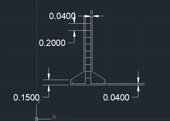
C.2.) c.s isolated footing
type l command to command box , and enter
- specify first point 1,1 and press enter
- specify next point ;at @1<0
- specify next point ;at @0.15<90
- specify next point ;at @0.38<150
- specify next point ;at @1.60<90
- specify next point ;at @0.24<180
- specify next point ;at @1.60<270
- specify next point ;at @0.38<200
- specify next point close or undo and press enter
- specify next point ;at @0.04<270
- specify next point ;at @0.38<0
- specify next point ;at @0.20<90
- specify next point ;at @0.20<90
- specify next point ;at @0.20<90
- specify next point ;at @0.20<90
- specify next point ;at @0.20<90
- specify next point ;at @0.20<90
- specify next point ;at @0.20<90
- specify next point ;at @0.20<90
- specify next point ;at @0.20<90
- specify next point ;at @0.20<90
- specify next point ;at @0.16<0
- specify next point close or undo nad press enter
- then type offset command and offset the top of 0.16 to throught 0.20 and press enter
- repeat the same offset process to 9 times.
- Then exist the command and enter
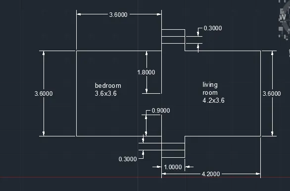
C.3.) Line diagram of a two bedroom building
type l command to command box , and enter
- specify first point 1,1 and press enter
- specify next point ;at @3.6<0
- specify next point ;at @0.30<270
- specify next point ;at @0.30<270
- specify next point ;at @0.30<270
- specify next point ;at @1<0
- specify next point ;at @0.30<90
- specify next point ;at @0.30<90
- specify next point ;at @0.30<90
- specify next point ;at @4.20<180
- specify next point ;at @0.30<90
- specify next point ;at @0.30<90
- specify next point ;at @0.30<90
- specify next point ;at @1<180
- specify next point ;at @0.30<270
- specify next point ;at @0.30<270
- specify next point ;at @0.30<270
- specify next point ;at @3.60<180
- then type offset command and offset the top of 1.00 to throught 0.30 and press enter
- repeat the same offset process to 2 times.
- Then exist the command and enter.
- then type offset command and offset the bottom of 1.00 to throught 0.30 and press enter
- repeat the same offset process to 2 times.
- Then exist command and press enter.
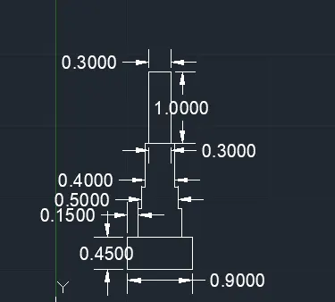
C.4).C.S load bearing wall showing foundation
type l command to command box , and enter
- specify first point 1,1 and press enter
- specify next point ;at @0.90<0
- specify next point ;at @0.45<90
- specify next point ;at @0.15<180
- specify next point ;at @0.60<180
- specify next point ;at @0.15<180
- exist and line command again
- specify first point pick the 0.40 point in x-axis.
- specify next point ;at @0.40<90
- specify next point ;at @0.05<0
- specify next point ;at @0.30<90
- specify next point ;at @0.05<0
- specify next point ;at @0.60<90
- specify next point ;at @0.05<0
- specify next point ;at @0.30<0
- specify next point ;at @0.05<0
- specify next point ;at @0.60<270
- specify next point ;at @0.05<0
- specify next point ;at @0.05<0
- specify next point ;at @0.40<270
- Exist and line command again enter
- specify first point to pick the same point 0.30
- specify next point ;at @1<90
- specify next point ;at @0.30<0
- specify next point ;at @1<270
- Then exist command and press enter.
C.5). Isometric drawings:-
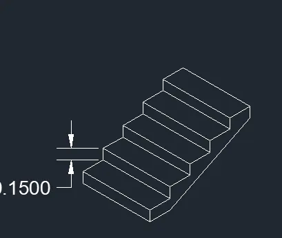
And first ds enter and off the snap on and grid on. and set isometric unit.
type l command to command box , and enter
- specify first point 1,1 and press enter
- specify next point ;at @0.15<90
- specify next point ;at @0.30<30
- specify next point ;at @0.15<90
- specify next point ;at @0.30<30
- specify next point ;at @0.15<90
- specify next point ;at @0.30<30
- specify next point ;at @0.15<90
- specify next point ;at @0.30<30
- specify next point ;at @0.15<90
- specify next point ;at @0.30<30
- specify next point ;at @1<110
- specify next point ;at @0.30<200
- specify next point ;at @0.15<270
- specify next point ;at @0.30<200
- specify next point ;at @0.15<270
- specify next point ;at @0.30<200
- specify next point ;at @0.15<270
- Exist line command and, offset the above line 1.00 to through 0.30 into 4 times.
- then adain offset the next line to 0.15 into 5 times and enter exist.
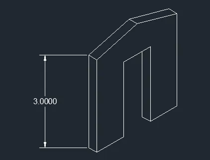
C.6). Isometric view of cable wall:-
type l command to command box , and enter
- specify first point 1,1 and press enter
- specify next point ;at @0.30<110
- specify next point ;at @1.00<30
- specify next point ;at @2.42<90
- specify next point ;at @1.00<30
- specify next point ;at @2.42<270
- specify next point ;at @3.00<90
- specify next point ;at @0.30<110
- specify next point ;at @1.15<120
- specify next point ;at @1.50<225
- Then exist command and press enter.