Creating a Residence Layout, Seating plan, Toilet and Utility room plan using AutoCad
Q1
Residence Plan:
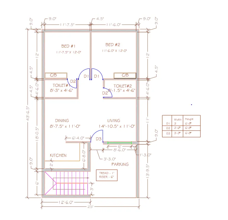
Sketch the layout of a residence as shown in the Figure 1. Consider all dimensions as reference to sketch the unit plan. Also the text in the layout are only for reference. Assume the missing dimensions. Also, refer the schedule for size of the doors.
AIM
Sketch the layout of a residence as shown in the figure given above.
INTRODUCTION
A residence plan is a set of construction or working drawings that define all the construction specifications of a residential house such as the dimensions, materials, layouts, installation methods and techniques.
PROCEDURE
Open the AutoCAD Application and create a new AutoCAD file with imperial settings. Set the units in 'Engineering' and precision (0'-0.0"), limits by typing 'LIMMAX' in command line (100',100') and zoom all by typing 'ZOOM' in command line (Zoom All).
1. Type 'XL' and enter to get 'XLINE'
- Create a vertical and horizontal 'XLINE'
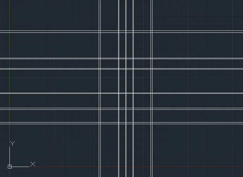
2. Type 'OFF' and enter to get 'OFFSET'
- From vertical XLINE, offset 9"and then offset 8'3" in the x direction
- From 9" (offset line from vertical XLINE), offset 11'7.5" in the x direction
- From 11'7.5" (offset line from 9"), offset 4.5" in the x direction
- From 4.5" (offset line from 11'7.5"), offset 11'6" in the x direction
- From 11'6" (offset line from 4.5"), offset 9" in the x direction
- From 11'6" (offset line from 4.5"), offset 8'1.5" in the -x direction
- From 8'1.5" (offset line from 11'6"), offset 4.5" in the -x direction
- From horixontal XLINE, offset 9"and then offset 6' in the x direction
- From 6' (offset line from 9"), offset 9" in the y direction
- From 9" (offset line from 6'), offset 6'8" in the y direction
- From 6'8" (offset line from 9"), offset 4.5" in the y direction
- From 4.5" (offset line from 6'8"), offset 11' in the y direction
- From 11' (offset line from 4.5 "), offset 4.5" in the y direction
- From 4.5" (offset line from 11'), offset 4'6" in the y direction
- From 4'6" (offset line from 4.5"), offset 4.5" in the y direction
- From 4'6" (offset line from 4.5"), offset 4.5" in the y direction
- From 4.5" (offset line from 4'6"), offset 12' in the y direction
- From 12' (offset line from 4.5"), offset 9" in the y direction
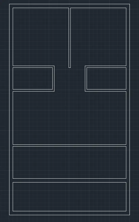
3. Use 'FILLET', 'TRIM', and 'ERASE' tools, remove all unnecessary lines to get the below figure
4. Type 'OFF' and enter to get 'OFFSET'
- From 4.5" (offset line from 4'6"), offset 11'9" in the -x direction
- From 11'9" (offset line from 4.5"), offset 9" in the -x direction
- From 9" (offset line from 11'9"), offset 6'4" in the -x direction
- From 4.5" (offset line from 6'8"), offset 9" in the -y direction
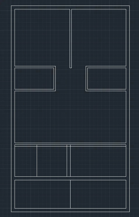
5. Use 'FILLET', 'TRIM', 'STRETCH', and 'ERASE' tools, remove all unnecessary lines to get the below figure
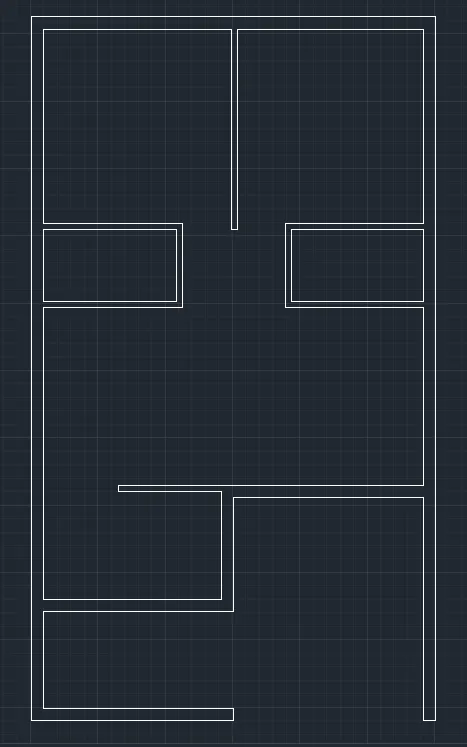
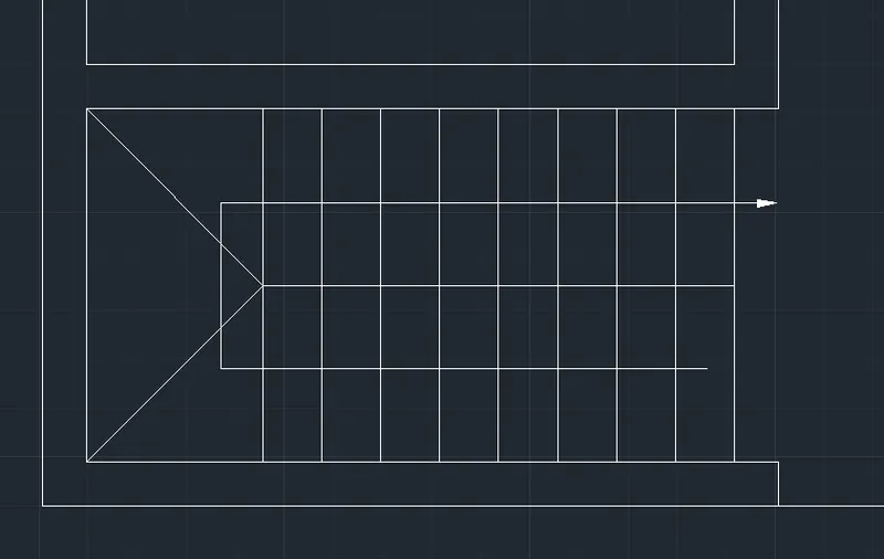
6. Draw the stairs
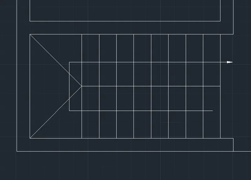
- Using 'LINE' tool, draw a line vertical from interior wall (Height 6'8") perpendicular to the horizontal line (Length 12'6") in the -y direction
- Using 'OFFSET' tool, offset the newly drawn line with a offset distance of 1' for 9 times in -x direction
- Using 'OFFSET' tool, offset the horizontal line (Length 12'6") with a offset distance of 3' in y direction
- Using 'LINE' tool, draw a line from the two corners to the intersecting the newly offset line with an angle of 45 degree.
- Using 'TRIM', and 'ERASE', remove all unnecessary lines to get the below figure
7. Draw the doors
D1:
- Using 'LINE' tool, draw a line 1', 2'10", 1' horizontally
- Using 'ROTATE' tool, select the 2'10" line and rotate it to 90 degree.
- Using 'CIRCLE' tool, draw a circle with start and radius with 2'10" line pointing the two ends as start and radius point respectively
- Using 'TRIM', remove all unnecessary lines and arcs
- Using 'COPY', 'MIRROR', and 'MOVE' tool, place the D1 at the necessary points according to the plan
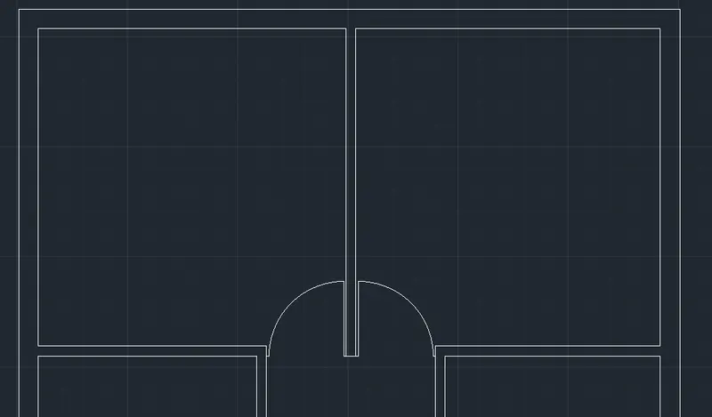
D2:
- Using 'LINE' tool, draw a line 1', 2'4", 1' horizontally
- Using 'ROTATE' tool, select the 2'4" line and rotate it to 90 degree.
- Using 'CIRCLE' tool, draw a circle with start and radius with 2'4" line pointing the two ends as start and radius point respectively
- Using 'TRIM', remove all unnecessary lines and arcs
- Using 'COPY', 'MIRROR', and 'MOVE' tool, place the D2 at the necessary points according to the plan
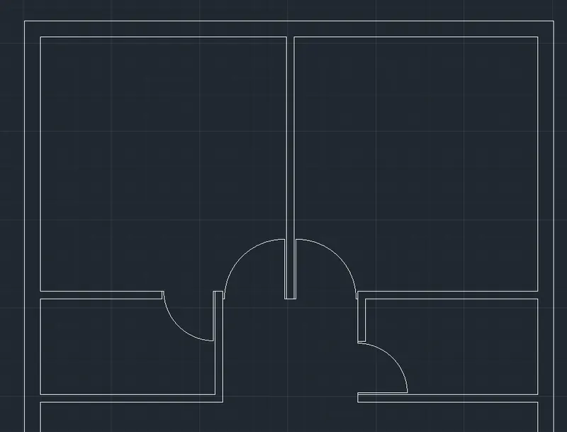
D3:
- Using 'LINE' tool, draw a line 1', 3'1", 1' horizontally
- Using 'ROTATE' tool, select the 3'1" line and rotate it to 90 degree.
- Using 'CIRCLE' tool, draw a circle with start and radius with 3'1" line pointing the two ends as start and radius point respectively
- Using 'TRIM', remove all unnecessary lines and arcs
- Using 'COPY', 'MIRROR', and 'MOVE' tool, place the D3 at the necessary points according to the plan
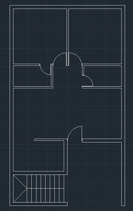
8. Draw the window
- Using 'OFFSET' tool, offset the vertical line (Height 9") with offset distance 1'3" in x direction
- Using 'OFFSET' tool, offset the new line with offset distance 6' in x direction
- Using 'LINE' tool, draw a line between the midpoint of the above two lines
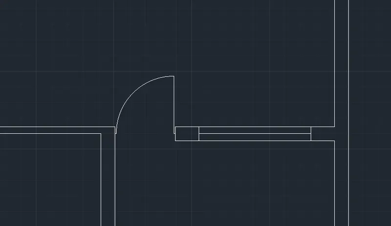
9. Draw the kitchen slab
- Using 'OFFSET' tool, offset the horizontal line (Length 11') with offset distance 2' in y direction
- Using 'OFFSET' tool, offset the vertical line (Height 6'8") with offset distance 2' in -x direction
- Using 'LINE' tool, draw lines to show the direction
- Using 'MLEADER', draw an arrow at the end of the line
- Using 'TRIM', remove all unnecessary lines
10. Draw cupboards
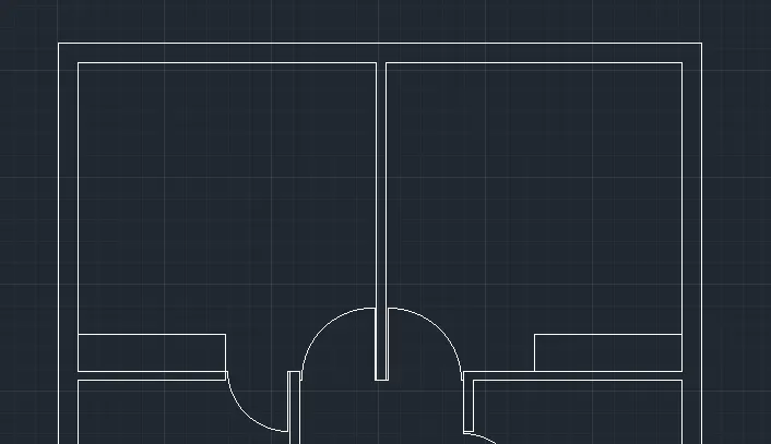
- Using 'RECTANGLE' tool, draw a rectangle of assumed dimension similar to the plan
- Using 'COPY' tool, place the C/B at necessary places according to the plan
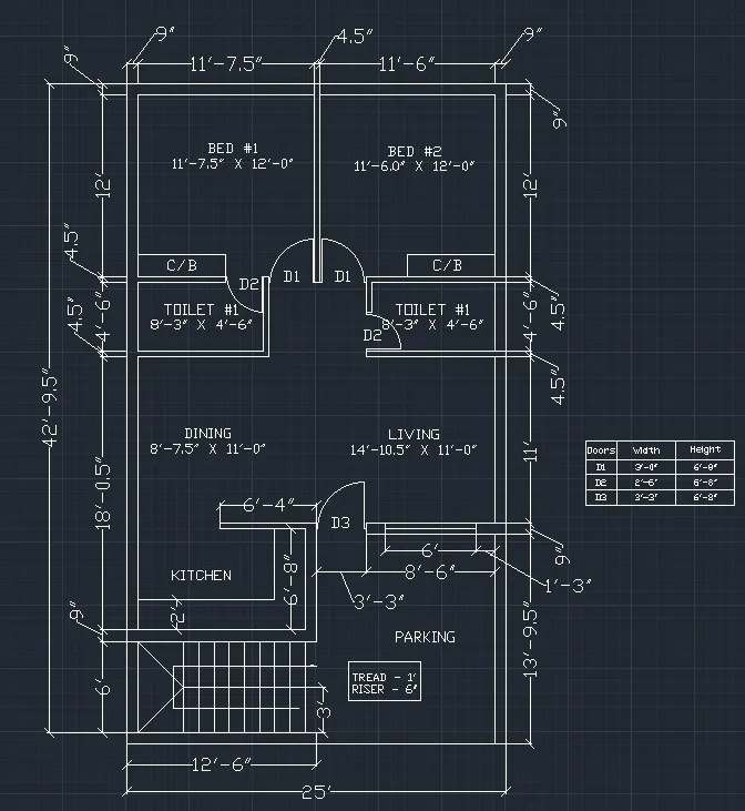
11. Labeling and dimension marking
- Using 'DIM' tool, mark all the dimensions
- Using 'MTEXT' tool, type all the labels
- Using 'TEXT', and 'TABLE' tools, mark the text in the table
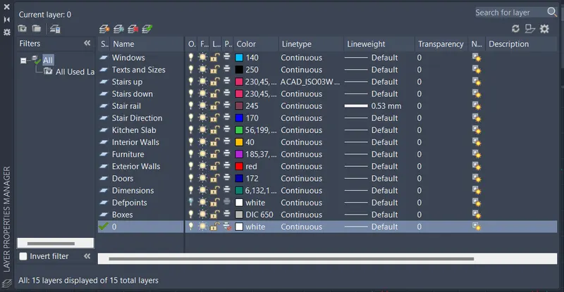
12. Assign layers to each segment of the plan using 'LAYER'
13. Hatch the walls using 'HATCH' tool
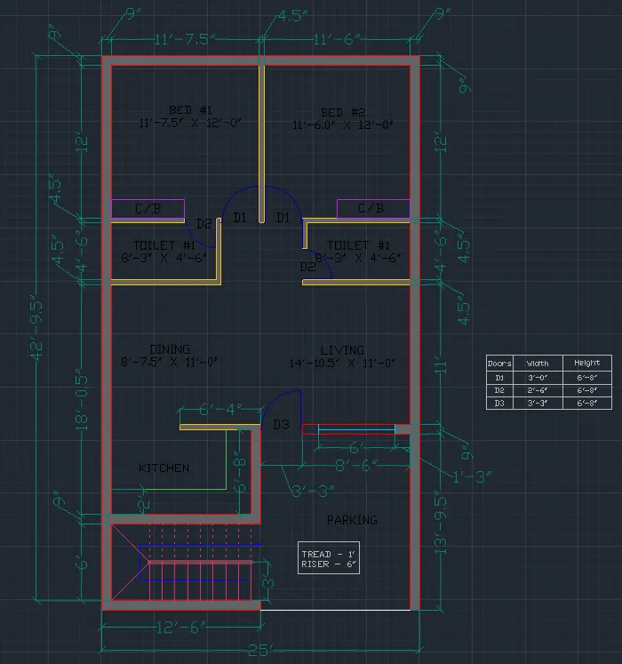
RESULT
The layout of a residence is sketched as per the given figure
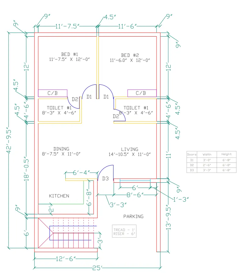
Q2
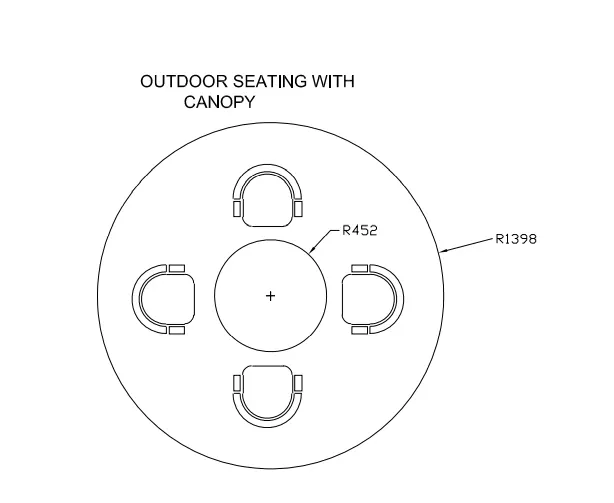
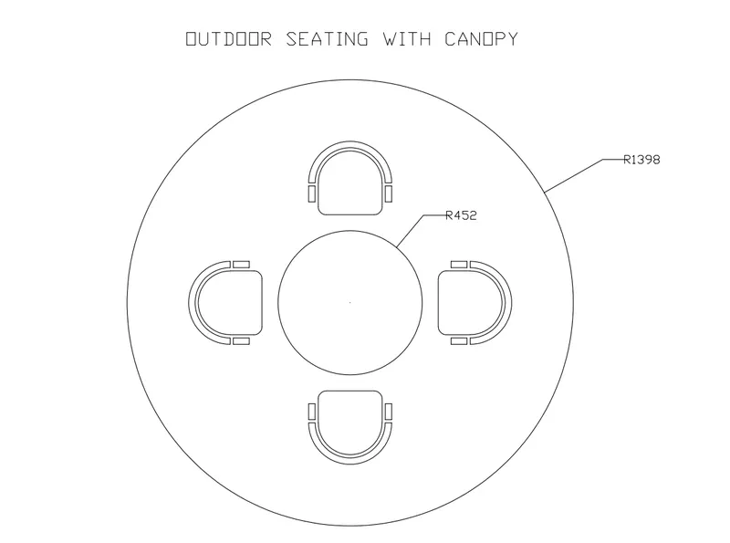
Sketch the seating plan for an outdoor canopy. Assume the dimensions for the seating. Also, consider the dimensions in mm.
AIM
Sketch the seating plan for an outdoor canopy.
INTRODUCTION
An outdoor canopy is a free-standing structure that is much like a tent except that it may or may not come with wall panels and does not have an attached panel that covers the ground.
PROCEDURE
Open the AutoCAD Application and create a new AutoCAD file with imperial settings. Set the units in 'Decimal' and precision (0), limits by typing 'LIMMAX' in command line (1000,1000) and zoom all by typing 'ZOOM' in command line (Zoom All).
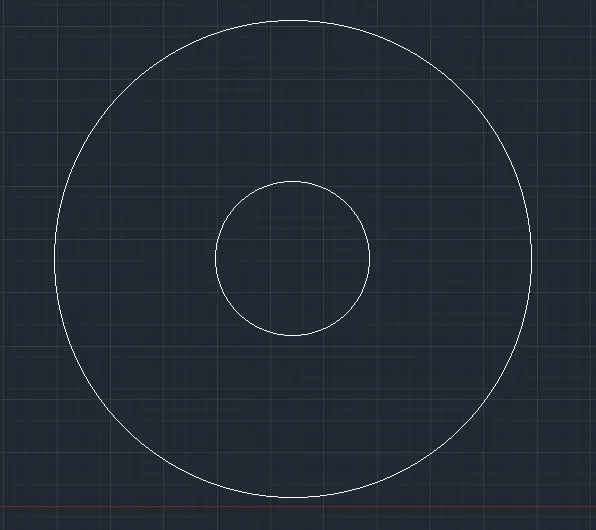
1. Type 'L' and enter to get 'CIRCLE'
- Draw two circle with radius 1398mm and 452mm with same orgin
2. Drawing of chair
- Using 'RECTANG' tool, draw a square of size (400,400)
- Using 'ARC' tool (Center, start, end), draw an arc with center of the arc same as the square (400,400), start point and end point as the midpoint of the two opposite sides of the square (400,400)
- Using 'OFFSET' tool, offset the arc with an offset distance of 20mm in the -x direction
- Using 'OFFSET' tool, offset the new arc with an offset distance of 40mm in the -x direction
- Using 'TRIM' tool, remove all unnecessary lines
- Using 'LINE' tool, draw a line connecting the two offset arcs on the both sides
- Using 'OFFSET' tool, offset the new line with an offset distance of 20mm in the x direction on both sides
- Using 'OFFSET' tool, offset the new line with an offset distance of 100mm in the x direction on both sides
- Using 'LINE' tool, draw line connecting the two offset lines on the both sides forming a rectangle
- Using 'FILLET' tool, make the right side corner of the square (400,400) fillet with a radius of 50mm
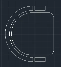
- Using 'MOVE' tool, move the chair inside the circle (R1398) with distance of 552mm from the center of the circle (R452)
- Using 'ROTATE' tool, copy the chair to the other 3 sides with base point as the center of the circle
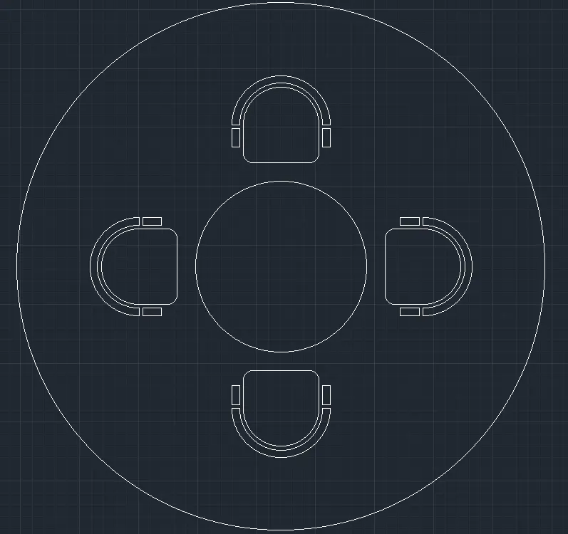
RESULT
The seating plan for an outdoor canopy is sketched and all dimensions are in 'mm'
Q3
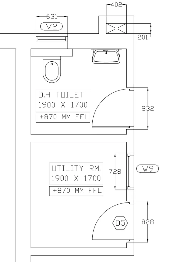
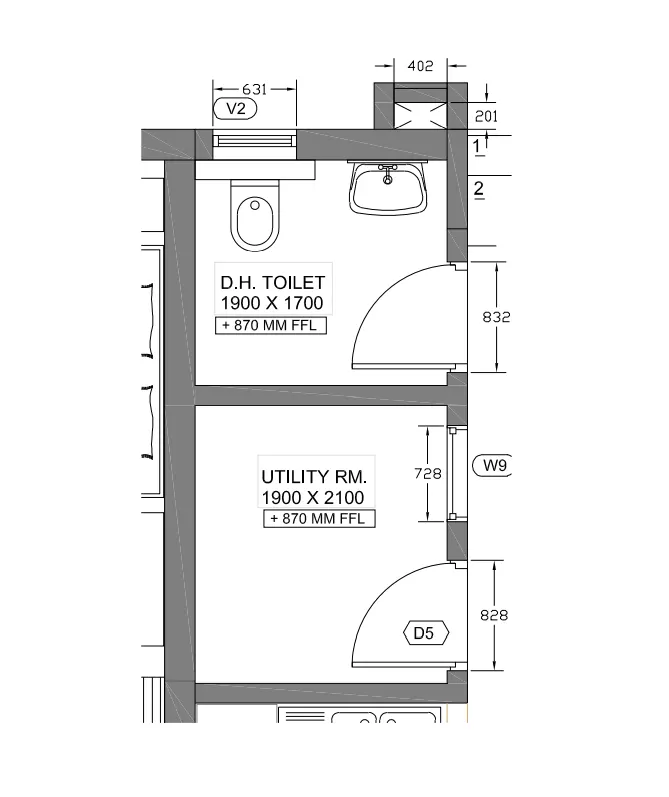
Sketch the part plan for the toilers and utilities room. Consider the outer wall thickness as 300mm and inner wall thickness as 150mm. Also, assume the missing dimension, Texts, dimensions, and hatches are only for references. Also, symbols for toilets and w/c are also for references.
AIM
Sketch the part plan for the toilers and utilities room as shown in the figure given above.
INTRODUCTION
Part Plan means a Plan of part of main Layout / Master Plan of a scheme for any residential, commercial, industrial and amenity plot / plots prepared due to occurring of any change at site.
PROCEDURE
Open the AutoCAD Application and create a new AutoCAD file with imperial settings. Set the units in 'Decimal' and precision (0), limits by typing 'LIMMAX' in command line (1000,1000) and zoom all by typing 'ZOOM' in command line (Zoom All).
1. Type 'XL' and enter to get 'XLINE'
- Create a vertical and horizontal 'XLINE'
2. Type 'OFF' and enter to get 'OFFSET'
- From vertical XLINE, offset 300mm and then offset 1900mm in the x direction
- From 1900mm (offset line from 300mm), offset 150mm in the x direction
- From 1900mm (offset line from 300mm), offset 402mm in the -x direction
- From 402mm (offset line from 1900mm), offset 150mm in the -x direction
- From horizontal XLINE, offset 150mm and then offset 2100mm in the y direction
- From 2100mm (offset line from 150mm), offset 150mm in the y direction
- From 150mm (offset line from 2100mm), offset 1700mm in the y direction
- From 1700mm (offset line from 150mm), offset 300mm in the y direction
- From 300mm (offset line from 1700mm), offset 201mm in the y direction
- From 201mm (offset line from 300mm), offset 150mm in the y direction
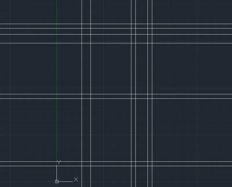
3. Use 'FILLET', 'TRIM', and 'ERASE' tools, remove all unnecessary lines to get the below figure
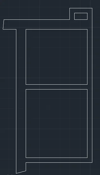
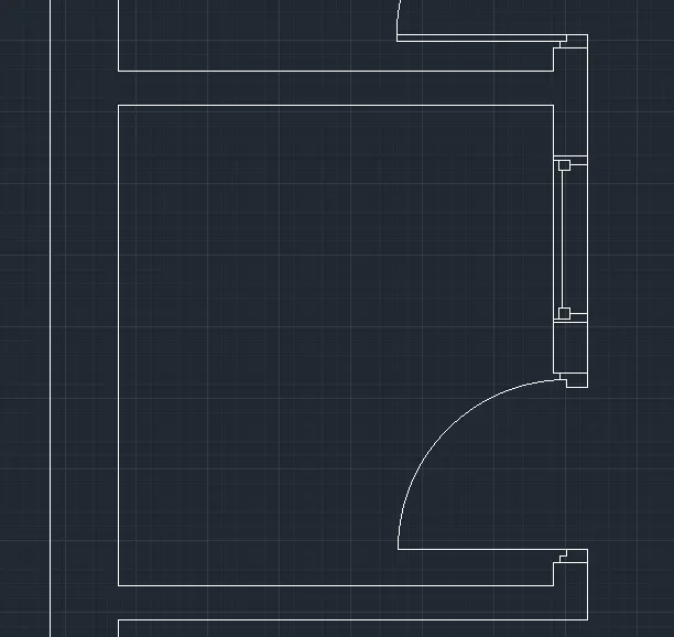
3. Providing the door openings
- Using 'LINE' tool, draw a line from the interior wall adjacent to the doors
- Using 'OFFSET' tool, offset the new line 100mm in the y direction for both doors
- Using 'OFFSET' tool, offset the new line 828mm and 832mm respectively in the y direction for both doors
- Using 'TRIM', remove all unnecessary lines
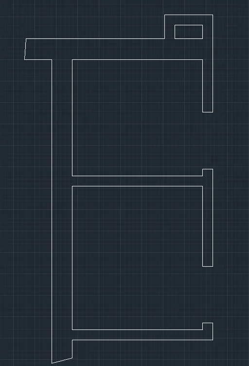
4. Draw the doors
- Using 'LINE' tool, draw a line from the openings 30mm in x direction, then 30mm in y direction and then 90mm in x direction
- Using 'COPY', 'MIRROR', place the shape in every end of the opening
- Using 'LINE' tool, draw a line from the above shape at this point (30mm in y direction) 738mm in the -x direction for door having width 828mm
- Using 'LINE' tool, draw a line from the above shape at this point (30mm in y direction) 742mm in the -x direction for door having width 832mm
- Using 'OFFSET' tool, offset the new line 30mm in the -y direction for both the doors
- Using 'CIRCLE' tool, draw a circle with start and radius with the new offset line pointing the two ends of the line as start and radius point respectively for both the doors
- Using 'TRIM', remove all unnecessary lines and arcs
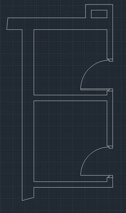
5. Draw the window
- Using 'LINE', 'RECTANG', draw the window with a width of 728mm
- Using 'COPY', 'MIRROR', place the window at the center of the wall
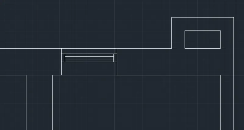
6. Draw the ventilator
- Using 'LINE', 'OFFSET' tools, draw the ventilator with a width of 631mm
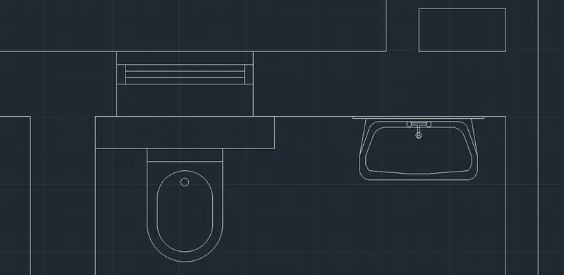
7. Draw closet and wash basin
- Using 'LINE', 'OFFSET', 'FILLET', 'ROTATE', 'MOVE', 'COPY' tools, draw the closet and wash basin
8. Labeling and dimension marking
- Using 'DIM' tool, mark all the dimensions
- Using 'TEXT' tool, type all the labels
- Using 'TEXT', and 'RECTANG' tools, mark the text in the BOX
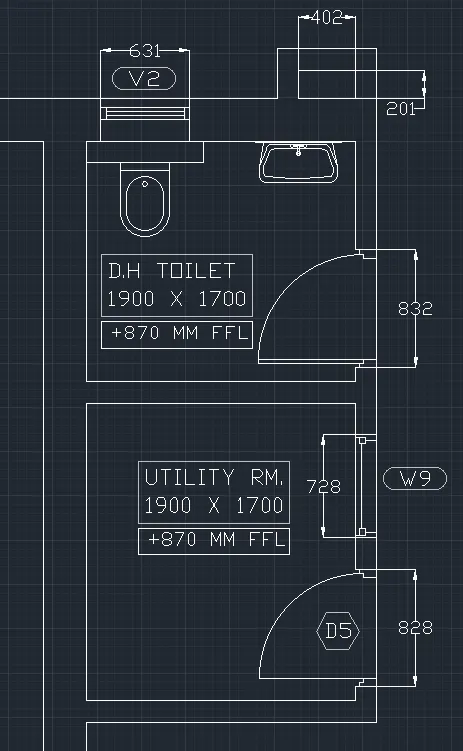
RESULT
The part plan for the toilers and utilities room is sketched as per the figure given. All dimensions are in 'mm'.