Creating a Residence Layout, Seating plan, Toilet and Utility room plan using AutoCad
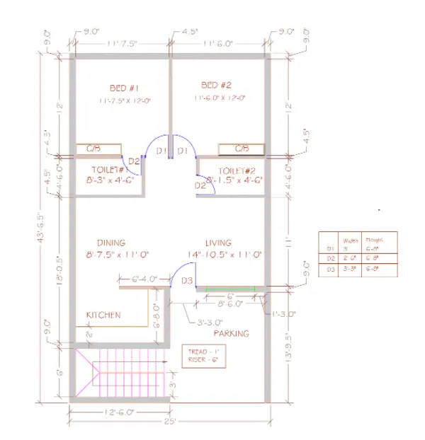
Aim - To draw a layout of given residence plan .
Introduction - i) Autocad is most appropriate software which is used to draw a architectural plan .
ii) For the students and learners , Residential layout is the best plan to practice anf learn the
autocad deeply .
iii) Following are the commands are used -
a) Constructio line (XL )
b) Offset (O)
c) Fillet (F)
d) Extend (EX)
e) Text command (T)
f) Units (UN)
g) Dimensions (DIM)
h) Trim command (T)
Procedure -
i) Open the New drawing sheet (Cntrl + N)
ii) Change the units - Engineering
iii) Precision - 0'-00" and Inches
Step by step procedure -
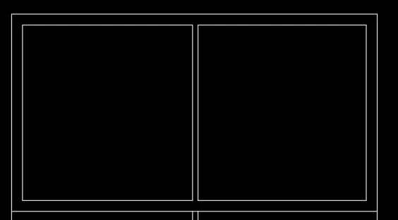
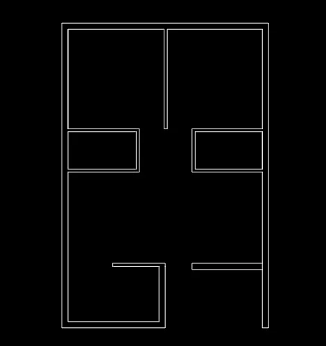
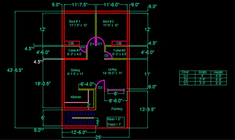
Step 1) Bedroom 1 and Bed room 2 -
i) Give Command XL and Draw the construction lines Horizontal and Vertical .
ii) Give the offset of 9" in horizontal and vertical lines .
iii) Command Offset and give offset of 12' in negative Y -direction
iv ) Take the offset of previous line at 4.5" as a wall thickness .
v) Similarly Give offset of 11'-7.5" in positive X direction .
vi) Again take the offset of previous line @4.5" ( Partition wall)
vii) Repeat the same command and take offset of 11'-6" in x direction
vii) Trim the remaining lines .
Step 2) Toilet ( Both sides )
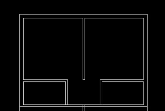
i) Take a offset of 4'-6" in negative Y direction from previous line as shown in above fig
ii) Give the wall thickness of partition wall by giving command Offset at 4.5" in negative Y direction
iii) Similarly take offset of 8'-3" in x direction and again 4.5" and 8'-1.5" in x direction and again 9" .
iv) Trim the remaining lines .
Step 3) Living Room and Dining Room and kitchen
i) Take the offset from Toilet at a distance 11' in Negative Y direction .
ii) Similarly for Dining room also . Take the offset of 11' from toilet in negative Y direction .
iii) Take the offset from Dining room for partition wall 4.5". and again offset of 6'-8" in negative Y direction'
iv) Take offset of 11'9" from living in nagative x direction for kitchen and add wall thickness 9".
v) From previous line take offset of 6'-4" in negative x direction .and add wall thickness 9" .
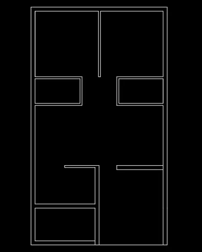
Step 4) Staircase and Parking -
iii) Take offset of 9" in negative y direction .
iv) Take offset of 12'-6" in x - direction . To make a box of staircase .
v) Take offset of 11'-9" in x - direction to make box of Parking .
vi) Trim the unwanted lines .
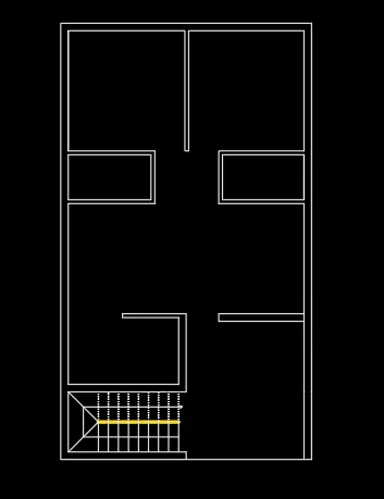
Step 5) Draw the stairs .
i) Take the riser - 6"
ii) Take the tread - 1'
iii) Divide the staircase by taking offset of 3'.
iv) Draw 9 offset as there are 9 risers and 8 steps .
v) Change the line type to ISO dash to the upward lines as it will not be visible in ground floor plan.
vi) Change the colour the color of ISO dotted line to yellow to make it visible .
vii) Make the direction of stairs by showing arrow.
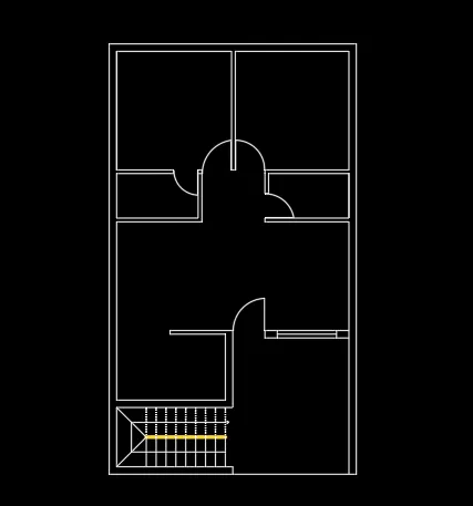
Step 6) Doors and Windows -
i) As the dimensions of doors are already given
D1 = 3'
D2 = 2'-6"
d3 = 3'-3"
ii) For Bed 1 and Bed 2 door dimension is D1
iii) For toilet it is D2
iv) For main door (Living Room ) it is D3
v) Make the necessary opening in particular room according to their door width.
vi) Draw the door by creating honges of 0.5" from both sides of wall for every rooms
vii) Command arc and select Start End and direction , and draw the arc .
viii) Repeat same procedure for all doors .
ix) As there are only one window is provided in given plan which is in Living Room .
x) Take the offset of 1;-3" on both side of the wall and draw the window of 6' as per given in plan.
Note - You can provide windows wherever it is required to make the rooms fresh and healthy and
to maintain the ventilation. ( Will consider only 1 window as per given plan)
Step 7) Kitchen slab and Cupboards
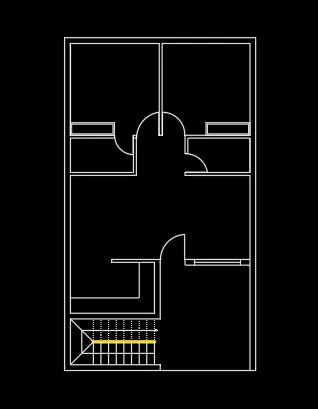
i) Command offset and give offset of 2' from the external wall staircase to draw kitchen slab .
ii) To draw cupboards give command Rectangle (Rec)
iii) Enter length = 5'9"
iv) Enter width =1'7.5"
v) Copy the same cupboard to Bed Room 2 .
Step 8) Units ans Dimensions and Text -
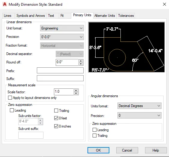
i) As we already set the units to Engineering and considered Decimal precison to Inches (0'-0.0")
ii) Give the command Dimensions (DIM)
iii) Select the primary units to Engineering and Select Decimal precision to (0'-0.0" )
iv) Set text height to 15" .
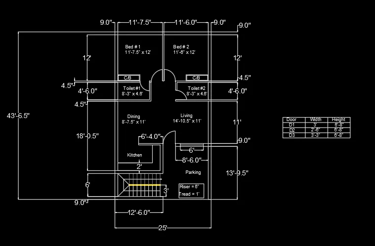
v) Measure the dimension and check it according to the given plan .
vi) After giving dimensions give command Text (T) .
vii) Draw the text box and you will see Text editor in Ribbon panel
viii) From there you can select whichever font you want and from Annotative set height of text .
Step 9) Layer properties .
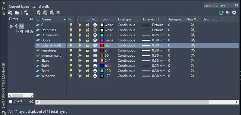
i) Command LA ( Layer ) .
ii) Create new layer for slabs , external walls , Internal walls , Dimensions , Text , furnitures , stairs , doors
iii) Name each layer as Kitchen Slab , Doors , Dimensions etc. and select diiferent colour and line weight and
line type .
iv) Select the object and place it .
Result - The layout of Residential plan is drawn
Problem 2)
Aim - To draw a seating plan of outdoor canopy .
Introduction - i) A canopy is a projecting hood or cover suspended over an altar , statue .
ii) A canopy are often large , free standing covering used to provide shade and protection
from the elements for a seated , outside area .
iii) It is made up of a large canvas of a durable fabric , strung over a metal frame .
iv) Followings Commands are used -
a) Circle
b) Extend
c) Offset
d) Trim
Procedure -
i) Open the New drawing sheet (Cntrl + N)
ii) Change the units - Decimals
iii) Precision - 0.0 and millimeters .
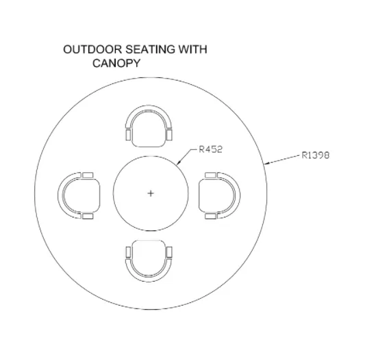
Step by step procedure to draw seating plan of outdoor canopy -
Step 1)
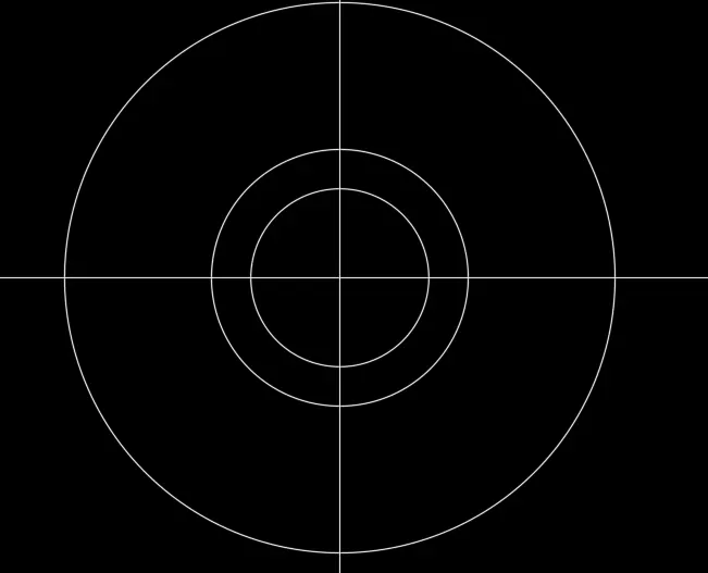
i) Command Circle (C)
ii) Select center point and draw a circle of radius 1398 mm
iii) Select same center point and draw a circle of radius 452 mm
iv) Draw the offset of 200 mm to this circle .
v) Command XL and draw horizontal and vertical construction lines to the circle .
Step 2) Chairs .
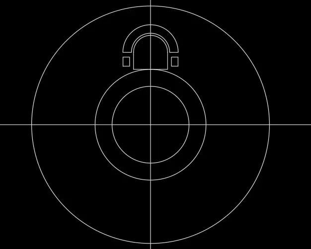
i) Command Rectangle (Rec)
ii) Enter the length = 400 mm
iii) Enter width = 200 mm
iv) Command Arc and select start center end and draw the arc .
v) Take the offset of 25mm of the arc and draw one more arc .
vi) Again take offset of 100 mm from last arc to draw a new arc and join the corners of both arc by line
vii) To draw the handle of chairs give command Rec and give dimension (77mm x 107mm)
Step 3)
i) Copy the chairs by giving command Copy (CO) .
ii) Command Miror and mirror it according to direction
iii) After mirroring give command Move and move it in such a way that its base should touches the offset of
200 mm circle .
iii) Repeat the same procedure to the other directions too .
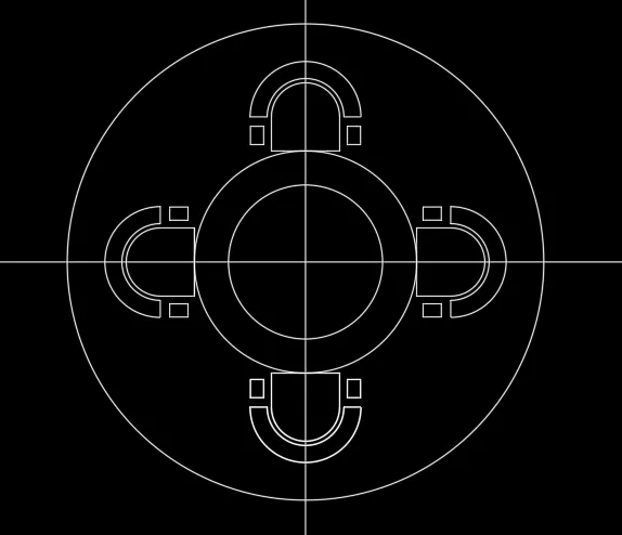
iv) After placing the chairs in all direction , Give command Fillet of radius 50mm to the base
of 400 mm x 200 mm of all rectangle .
iv) Trim the unwanted lines and give the dimensions .
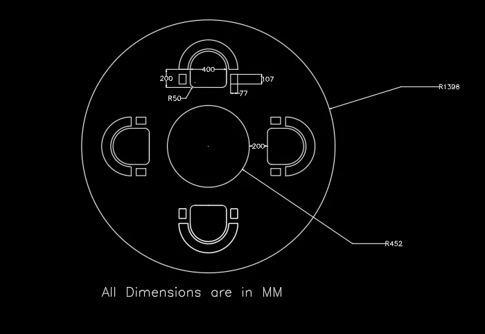
v) Mentioned the assume dimesnsions .
vi) Give the command DIM - and measure the dimensions .
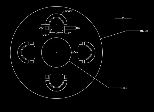
Results - The seating plan for an ourdoor canopy is drawn .
Problem 3)
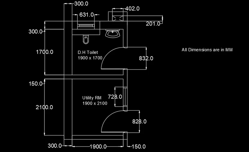
Aim - To draw a part plan for toilets and utilities room .
Introduction - i) A toilet room consists of lavatory , sinks and other accessones
ii) A utility room mainly used for laundry area . It has other functions too .
iii) A utility room contains various equipment like washing machines , clothes iron ,
drier etc .
iv) Following commands are used -
a) XL ( Construction line )
b) Line
c) Arc
d) Offset
e) Trim
f) Fillet
g) Dimensions
Procedure -
i) Open the New drawing sheet (Cntrl + N)
ii) Change the units - Decimals
iii) Precision - 0.0 and millimeters .
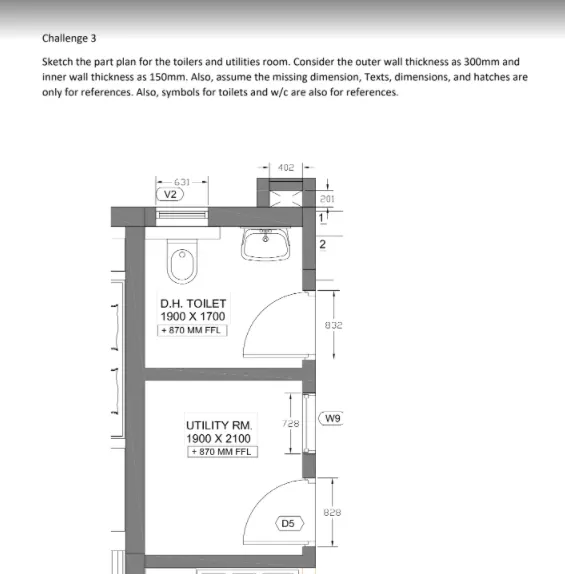
Step by step procedure to draw a part plan for toilets and utilities .
Step 1)
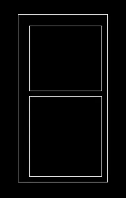
i) Give command XL and draw horizontal and vertical construction lines .
ii) Command Offset of 300 mm to draw a external wall thickness in positive x direction .
For toilet -
iii) Take the offset of 300 mm from top for external wall thicknes in negative y direction .
iv) Again command offset and give offset of 1700 mm in negative y direction .
v) Now for Vertical line give offset of 1900 mm drom (XL - V ) and again draw a external wall of 150 mm
vi) Complete the line plan for toilets .
For Utility Room -
i) Take the offset from the bottom line of toilet and give internal wall thickness as 150 mm
ii) Take the offset From the internal wall between toilet and utility room of 2100 in negative y direction .
iii) And again draw wall thickness of 150 mm to bottom of utility room by giving command offset .
iv) Similarly repeat the procedure for vertical offset . Extenf the line of toilet as it as same dimensions
i.e 1900 mm .
v) Extend the wall thickness too by givimg command (EX) .
vi) Trim the remaining lines
Step 2)
i) Draw the duct of by giving command Rec
ii) Enter length = 201 mm
iii) Enter width = 402 mm
iv) Give the offset of 150mm to this rectangle to draw wall thickness .
Doors
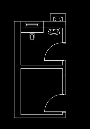
i) Draw the door by making width of 832 mm for toilet
ii) Draw the hinges by taking offset of 12 mm on both sides of wall .
iii) Given Coomand Arc - Select Start end and direction and draw the arc .
iv) Similarly repeat the same procedure for Utility room Door
v) Make a width of 828 mm .
vi) Give hinges of same dimensions
vii) Command arc and select start end and directions and draw the arc.
Step 3) Utilities -
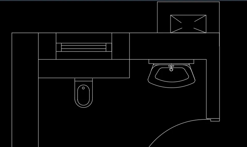
i) Draw the utilities ( Sinks and Toilet )
ii) Assume the dimension
iii) Used command Arc , Fillet , Ellipse .
Step 4) Dimensions and text -
i) Command Dimensions .
ii) Select Primary units as Decimals (0.00) as milimeters .
iii) Select the height as 200 mm
iv) And arrrow size as 100 mm
v) Measure the dimensions as per given plan .
vi) Give the dimensions .
Text -
i) Give command text
ii) From text editor ( in Ribbon panel ) select Annotative as size 100 mm
iii) Select suitable font and text height as 100 mm
iv) Give the naming as per given plan .
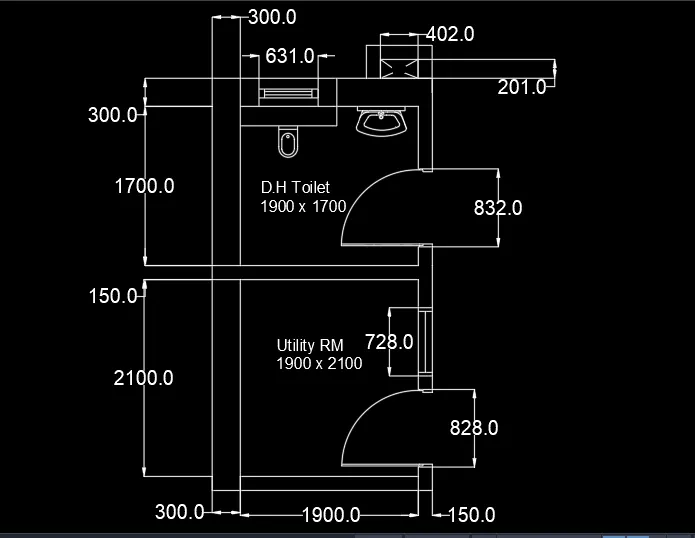
Results - The plan of Toilets and Utilities room is drawn .