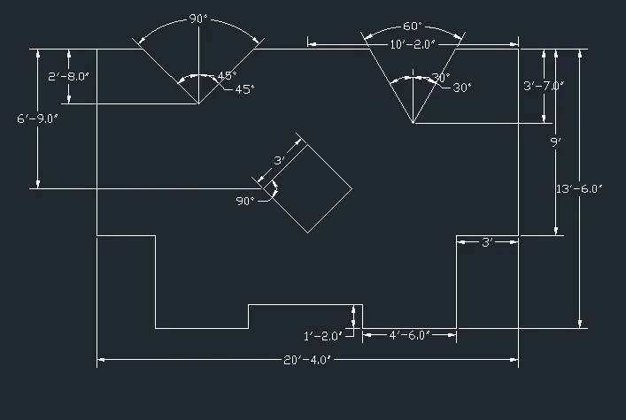
Drafting of various geometries using Chamfer, Fillet tool in AutoCad
Aim : Drafting of various geometries using chamfer, fillet tool in autocad
Introduction :
The autocad is used to draw the various geometry.The line, circle, fillet, mirror etc are used to draw the the given geometry. Chamfer is the command that used to draw the slang edges. fillet is used to draw curved edges.
1. Drawing No 1 :
Procedure :
- Open the new file select the imperial and select the advance setup, set the unit of measurment as decimal of the precision 0.00, select the angle measurment and set the direction of angle of measurment, and slelect the plot area.
- Select the line command specify the starting point and give the length of the line as 3.00 units, @2.12 < 45, @2.83 < 135 then 2 units last select as a close.
- Offset the 3 units line at a distance of 1 units and 2.50 units.
- Draw the line of length 1.5 units vertical from the starting point from the drawing and the intersection between this vertical line and the horizonatal line 1 units as centre draw circle with diameter of 1.20 units.
- The intersection between 1.5 vertical line and the horizonatal line of 2.5 units as centre draw the circle with diameter of 0.80 units.
- Erase the projection line for drawing the centre of the circle.
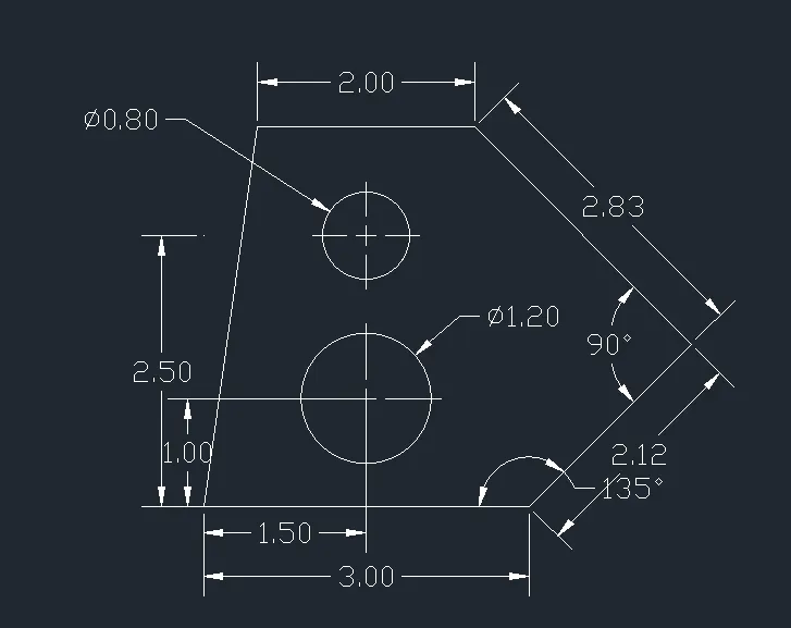
2. Drawing No 2 :
Procedure :
- Open the new file select the imperial and select the advance setup, set the unit of measurment as architectutral, select the angle of the measurment and set the direction of angle of measurment, and slelect the plot area.
- Select the line command specify the starting point and the second point as @2'10" < 45, keeping the cursor vertical enter the 1'9", left at 8', down at 2'5"
- Select the polar tracking as a 30,60,90 ....
- kepping the cursor downward right side enter line length as 3' (in the direction of polar tracking projection), draw a line of 2'6" pependicular to 3' line.
- Select the close in command box.
- give annotation to all.
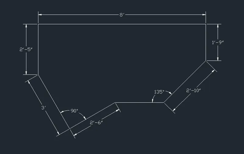
3. Drawing No 3 :
Procedure :
- Open the new file select the imperial and select the advance setup, set the unit of measurment as Engineering, select the angle of the measurment and set the direction of angle of measurment, and slelect the plot area.
- Slect the line command specify the starting point of the line.
- enter the length of the line as 2'6.5" in -X axis, 3'3" in downward ie -Y axis, 5'0.1" in +X axis, 1'6" in +Y axis ie upward and close that present in the command box.
- offset the 5'0.1" line at a distance of 1'6" and 3'3" line at a distance of 1'3".
- Draw the circle of the diameter 1'6" with centre as the intersectin of the offset line.
- Erase the intersection line.
- Give the annotation.
4. Drawing No 4 :
Procedure :
- Open the new file select the imperial and select the advance setup, set the unit of measurment as decimal of the precision 0.00, select the angle measurment and set the direction of angle of measurment, and slelect the plot area.
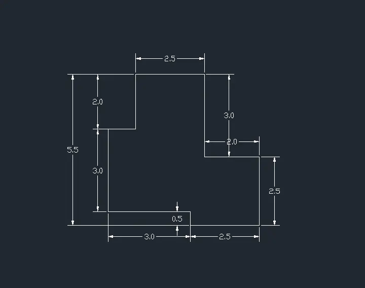
- Select the line command specify the starting point of the line and the ortho is on.
- Enter 3 units in downward direction, 3.0 units in right, 0.5 units in downward, 2.5 units in horizontal right direction, 2.5 units in upward, 2.0 units in left direction, 3.0 units in upward, 2.5 units in left direction, 2.0 units in downward direction and close the line command.
5. Drawing No 5 :
Procedure :
- Open the new file select the imperial and select the advance setup, set the unit of measurment as decimal of the precision 0.00, select the angle measurment and set the direction of angle of measurment, and slelect the plot area.
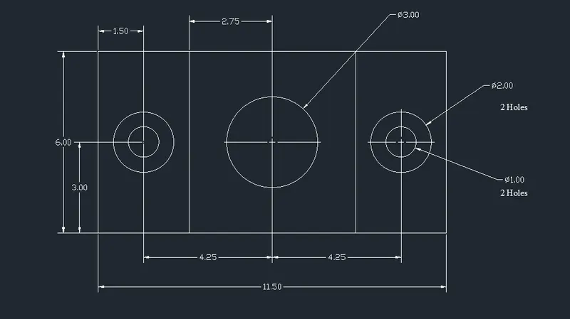
- Select the line command specify the starting point of the line.
- enter the length of the line as the 5.75 units in left side 6 units in downward and 5.75 units in right direction and close the line command.
- Offset the the vertical 6 unit line at a offset distance of 1.50 units in right side.
- Offset the horizontal 5.75 units in upward direction at a offset distance of 3 units
- Select the circle command with centre and diameter. select the centre of the circle as intersectin of the offset line at a diameter of 1 units.
- Erase the offset lines.
- select the offset form the ribbon select the object of 1 unit circle with the offset distance of 0.5 units in outward.
- select the offset form the ribbon select the object of 6 unit line with the offset distance of 2.75 units in left direction.
- select the mirror option. select the full drawing and enter first point as the right 6 unit bottom point and end point as top corner of the line.select the erase option no.
- on the midpoint object snap.
- Select circle centre with diameter from the ribbon with centre as middle point of 6 unit middle line at the diameter of 3 units.
- Erase the centre 6 units line.
Drawing No 6 :
Procedure:
- Open the new file select the imperial and select the advance setup, set the unit of measurment as decimal of the precision 0.00, select the angle measurment and set the direction of angle of measurment, and slelect the plot area.
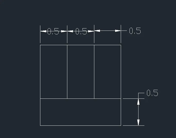
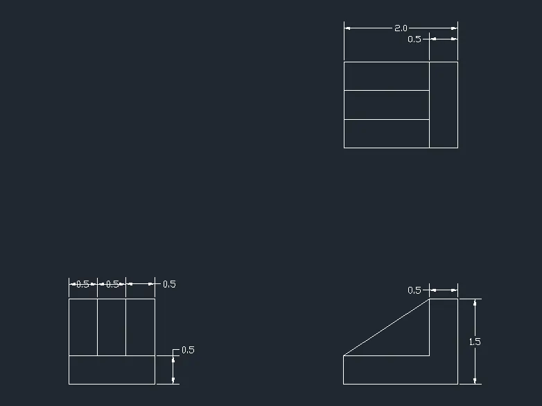
- Select the rectangle from the ribbon give the length of the rectangle as 1.5 and width as 0.5 units.
- From the top corner of the rectangle draw the line of the length 1 units.
- Offset this line with offset distance of 0.5 units in right direction.
- join all the all offset line by line command.
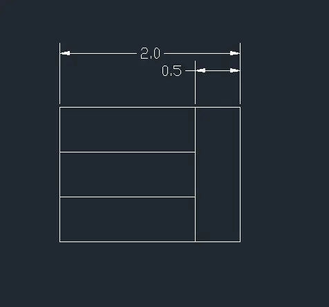
- Select the rectangle from the ribbon give the length of the rectangle as 0.5 and width as 1.5 units.
- From the left corner of the rectangle draw the line of the length 1.5 units.
- Offset this line with offset distance of 0.5 units in upwards.
- join the all offset lines by line command.
- extend the lines from the the both above diagram.
- Join the the points of intersection by the the line command.
- trim the unwanted lines.
Drawing No 7 :
Procedure:
- Open the new file select the imperial and select the advance setup, set the unit of measurment as decimal of the precision 0.00, select the angle measurment and set the direction of angle of measurment, and slelect the plot area.
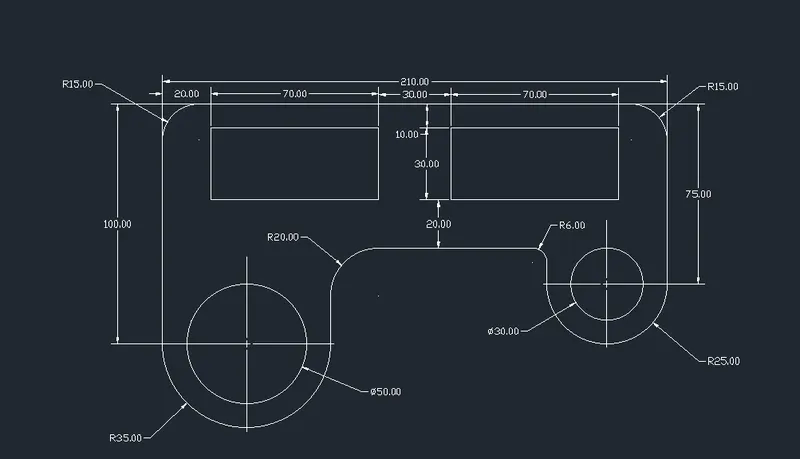
- Select the line command give the length of the line as 210 units in left side, 100 units in downward, 70 units in right side, 40 units upward, 90 units in right direction, 15 units in downward, 50 units in right direction, select the close command in the command box.
- Select the fillet option from the ribbon, select the radius from command box give the fillet of radius 15 units and select the 210 unit and 100 unit line.
- Select the fillet option from the ribbon and select 210 unit and 75 unit line
- Select the fillet option from the ribbon, select the radius from command box give the fillet of radius 20 units and select the 40 unit and 90 unit line.
- Select the fillet option from the ribbon, select the radius from command box give the fillet of radius 6 units and select the 15 unit and 90 unit line.
- Select the circle with centre and diameter. specify the centre of the circle as the midpoint of the 70 unit line with an diameter of 50.
- Select the circle with centre and diameter. specify the centre of the circle as the midpoint of the 50 unit line with an diameter of 30.
- Select the arc from the ribbon with start, end and radius.
- starting point of the arc is the intersection point of 100 and 70 unit line and end point is the intersection point of 70 and 40 unit line with an radius of 35.
- Select the arc with starting point of the arc is the intersection point of 15 and 50 unit line and end point is the intersection point of 50 and 75 unit line with an radius of 25.
- Erase the 70 unit line and 50 unit line.
- Offset the 210 unit line by a offset distance of 10 in downward.
- Offset the 100 unit line by a offset distance of 20 in right direction.
- Enter REC select first corner of the rectangale as intersection of these offset line and enter @70,-30.
- Offset the 75 unit line by a offset distance of 20 in right direction.
- Enter REC select first corner of the rectangale as intersection of these offset line and enter @-70,-30.
- Erase the all offset lines.
8. Drawing No 8:
Procedure:
- Open the new file select the imperial and select the advance setup, set the unit of measurment as decimal of the precision 0.00, select the angle measurment and set the direction of angle of measurment, and slelect the plot area.
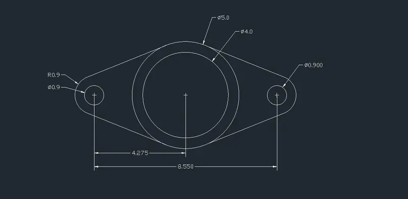
- Select the line command, specify the starting point of the line and enter length of the line as the 8.55
- Select the circle from the ribbon with centre and the diameter.
- select the centre of the circle as the starting point of the line enter the diameter of circle as 0.9 units. Draw another circle with centre as a end point of the line with diameter of 0.9 units.
- Draw a circle with with centre as a midpoint of the line with a dimeter of 4.
- Draw a circle with with centre as a midpoint of the line with a dimeter of 5.
- Select the circle from the ribbon with centre and the radius.
- select the centre of the circle as the starting point of the line enter the radius of circle as 0.9 units.
- Draw another circle with centre as a end point of the line and radius of 0.9 units.
- Join the outer circle by a tangent using the line command.
- Trim the unwanted lines.
9. Drawing No 9:
Procedure :
- Open the new file select the imperial and select the advance setup, set the unit of measurment as Engineering, select the angle of the measurment and set the direction of angle of measurment, and slelect the plot area.
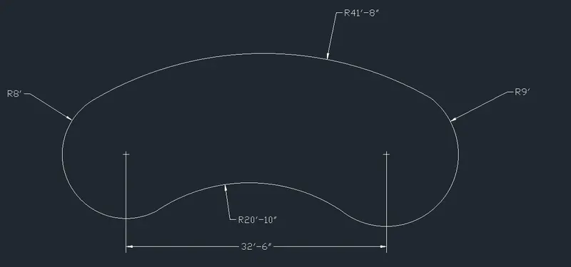
- Select the line command and specify the starting point of the line and length of the line is 32'6".
- Select the circle with centre, radius.
- Select the centre of the circle as the first point of the line and radius of 8'.
- Draw the another circle with centre is the end point of line with an radius of 9'.
- Select the arc with start, end and radius.
- select first point of the arc is the top of the 9' circle and end point is top of 8' circle with an radius of 41'8".
- draw with thr first point of the arc is the bottom of the 9' circle and end point is bottom of 8' circle with an radius of 20'10".
- Trim the unwanted lines.
Drawing No 10:
Procedure :
- Draw the rectangle with the same length and width.
- Draw another rectangle with bigger size compared with the first rectangle with same length and width.
- Select rotatefrom the ribbonand select the object and give the base point as geometric centre and select the copy from command box and enter the angle of rotation.
- trim the crossing lines.
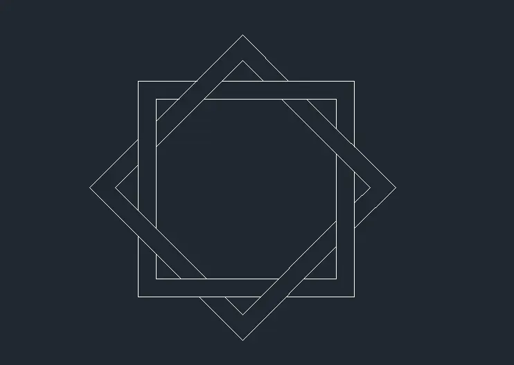
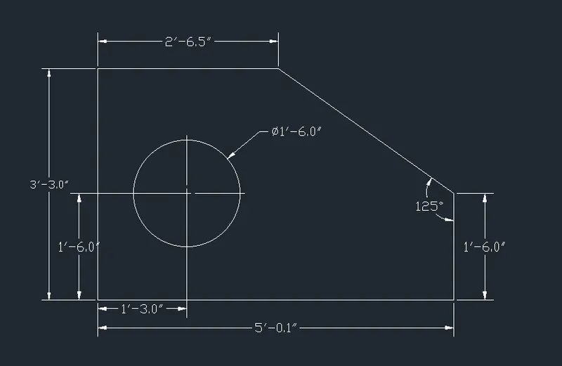
Drawing No 11:
Procedure :
- Open the new file select the imperial and select the advance setup, set the unit of measurment as Engineering, select the angle of the measurment and set the direction of angle of measurment, and slelect the plot area.
- Select the line command specify the starting point of the line. enter 9' in downward direction.
- 3' in horizontal left direction, 4'6" in vertical downward direction, 4'6" in left horizontal direction, 1'2" in upward direction, 5'4" in horizontal left direction, 1'2" in vertical downward direction, 4'6" in left direction, 4'6" in vertical upward, 3' in horizontal left direction, 13'6" in vertical upward direction, close the line command.
- offset the 20'4" line in downward at a offset distance of 6'9" and vertical 13'6" line at a offset of 10'2"
- with use of rectangle command draw the rectangle of length and width of 3' with geometry centre of the rectangle as the intersection of offset lines.
- Rotate this rectangle at an angle of 45 degree
- draw the line 5'1" in horizontal right direction at 2'8" downward direction from top left corner and polar tracking on draw the line with 90 angle
- draw the line 5'1" in horizontal left direction at 3'7" downward direction from top right corner and polar tracking on draw the line with 60 angle
- Trim the all unwanted lines and erase the unwanted lines.