Creation of Column Schedule and Drawing Template using AutoCad
Aim : To create column schedule, Window schedule, drawing template and beam details by using the autocad.
Introduction:
It necessary to provide the column schedule and window schedule which contains the diameter of the bar, number of bars that provided in the column, Spacing of the stirrups. Structural columns are identified in a column schedule by intersecting grid lines and by their top and bottom constraints and the offsets. They are placed into the column schedules according to these identification.
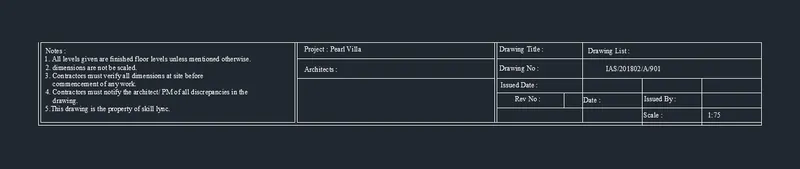
The drawing template which helps in the identification of the project name, the name of the structural c onsultant, architect and it incldes some notes, the number of revision that carried out in the drawing which is better helpful in construction.
The beam is a structural element that primily resist the load applied laterally to the beam axis. the mode of deflection is primarly by bending. the load applied in the beam result in reaction forces at the beam supports points.
1. Column schedule
Commands used
- Line Command
- Single line text
- Offset Command
- Donut command
- Copy command
- Trim command
- Explode Command
Propcedure :
Step 1
- Open the new file select the imperial
- UN enter select the engineering and select the precision.
- LIMMAX enter and give the plot area and Z enter A enter
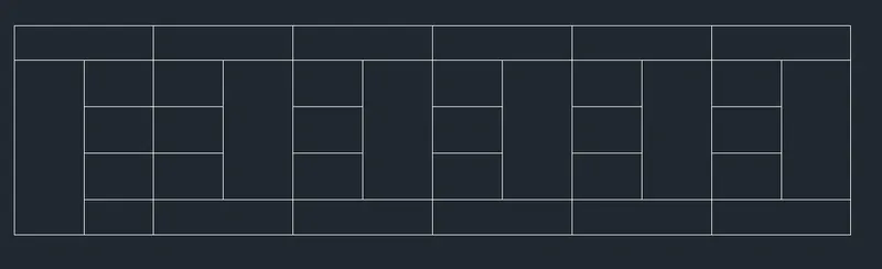
- Draw the table as shown.
Step 2 : C1
- Draw the rectangle of the size 9" x 24"
- O Enter and type the offset distance of 0.8" offset rectangle inside.
- Explode the rectangle and it is devided into 4 segment and are connected.
- Select the donut give the internal diameter of 0.1 and outer diameter of 20mm (0.8 inch) and are placed as shown in figure.
- Select the donut give the internal diameter of 0.1 and outer diameter of 12mm (0.47 inch) and are placed as shown in the figure. it is denoted as a
Step 3 : C1a
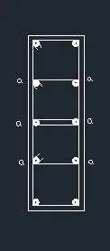
- Draw the rectangle of the size 9" x 24"
- O Enter and type the offset distance of 0.8" offset rectangle inside.
- Explode the rectangle.
- Offset the top line with 4.48 inch into 5 segments as shown.
- Select the donut give the internal diameter of 0.1 and outer diameter of 16mm (0.6 inch) and are placed as shown in the figure
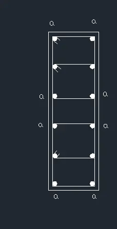
Step 3 : C2
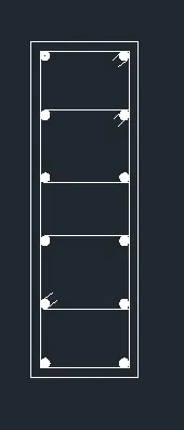
- Draw the rectangle of the size 9" x 24"
- O Enter and type the offset distance of 0.8" offset the rectangle inside.
- Explode the rectangle.
- Offset the top line with 4.48 inch into 5 segments as shown.
- Select the donut give the internal diameter of 0.1 and outer diameter of 20mm (0.8 inch) and are denoted as "a" are given in 8 nos.
- Select the donut give the internal diameter of 0.1 and outer diameter of 12mm are given in 4 numbers.
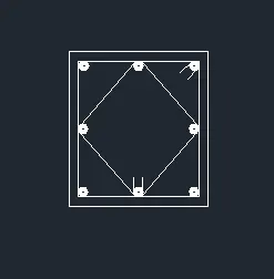
Step 4 : C2a
- Draw the rectangle of 9"x 10 "
- Offset this rectangle with offset distance of 0.8" inside.
- Select the donut give the internal diameter of 0.1 and outer diameter of 16mm (0.6 inch) are given in 8 nos are placed as shown in figure.
- The centre commands are connected by a line command.
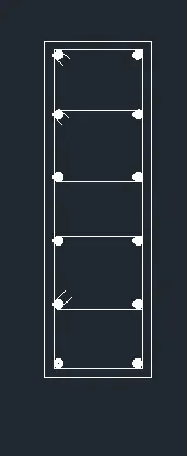
Step 5 : C3
- Draw the rectangle of the size 9" x 21"
- O Enter and type the offset distance of 0.8" offset rectangle inside.
- Explode the rectangle.
- Offset the top line with 3.88 inch into 5 segments as shown
- Select the donut give the internal diameter of 0.1 and outer diameter of 16mm (0.6 inch) and are placed of 12 numbers.
- These are placed equal distance apart.
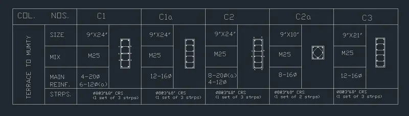
Step 6:
- By using the single line text command the text are typed.
- All columns are placed
2. Window Schedule
Commands Used
- Table Command
- Dtext command
Procedure :
- Open the new file select the imperial
- UN enter select the engineering and select the precision.
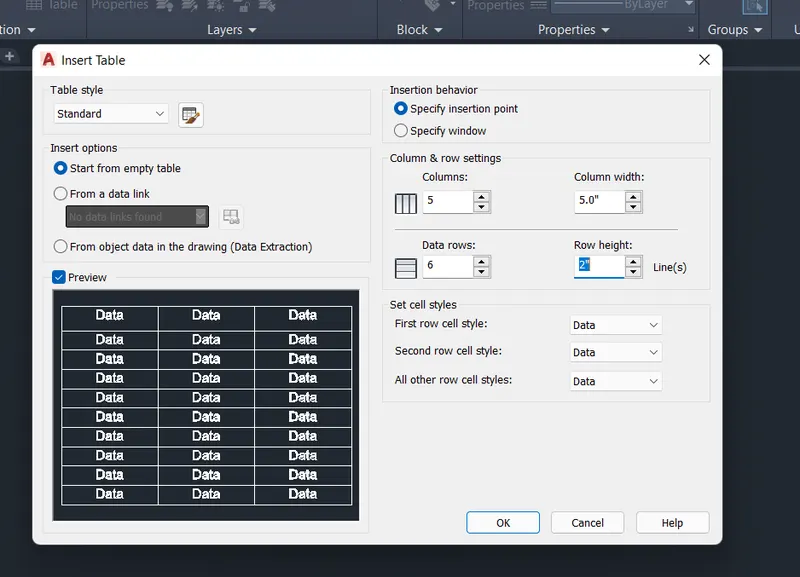
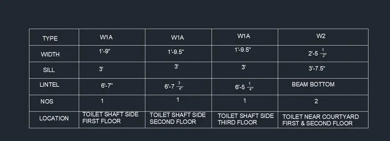
- Select the table command give the columns of 5 numbers and rows of 6 numbers and give the column width, row height.
- Adjust the column width and row height as per requirement.
- Select the single line text and enter the window schedule details in tabular.
3. Drawing of the template
Commands are used
- Units command
- Limits command
- Line command
- Mtext command
- offset command
- Trim command
- Extend command.
procedure:
- Open the new file select the metric
- UN enter select the decimal and select the precision.
- Draw the table by using the line command.
- Select the mtext command enter required height of the text and font
- enter the details of the template as shoen in below.
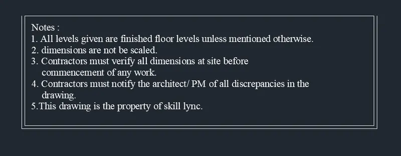
- Use the single line text command enter detalis of the the template as shown in the figure.
4. Drawing schedule
Commands used
- Units command
- Limits command
- Table command
- Single line text
Prosedure :
- Open the new file select the metric
- UN enter select the decimal and select the precision.
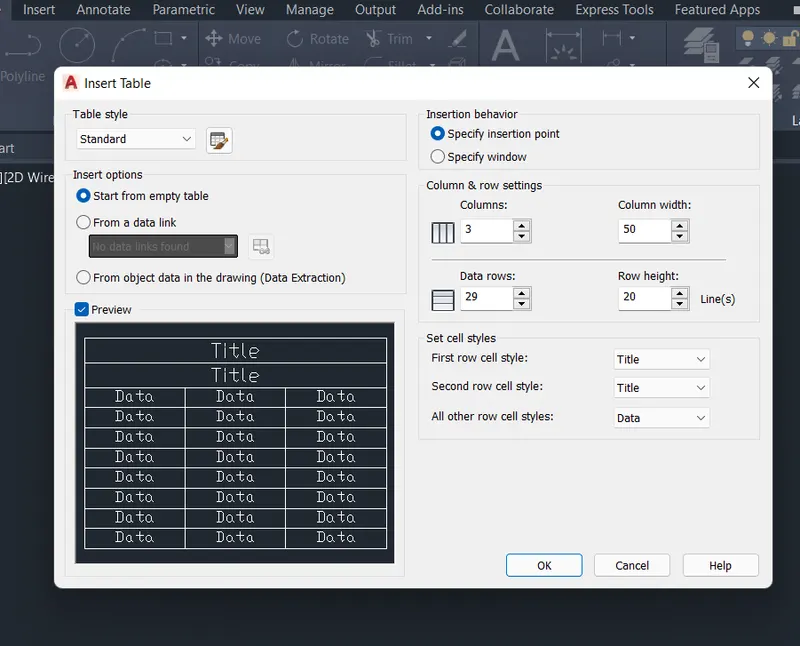
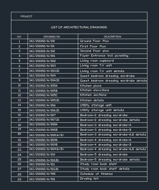
- Select the table command give the columns of 3 numbers and rows of 30 numbers and give the column width, row height.
- Adjust the column width and row height as per requirement.
- Select the single line text and enter the height of the text and required font.
- Enter the drawing schedule details in tabular table.
5. Beam details
Commands Used
- Units command
- Limits command
- Zoom command
- line command
- Leader command
- Linear dimension
- Hatch
- Offset
Procedure :
- Open the new file select the metric
- UN enter select the decimal and select the precision.
- Enter limmax enter plot area of 10' x 10'
- Z enater A enter
- Draw The line by using the line command
- Offset this line by a distance of 9"
- Join these two lines
- draw a line right side horizontal line at certain height from the bootom point i.e ground level
- offset this line with offset distance of 9" above i.e top level
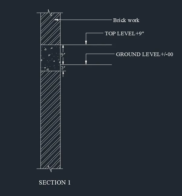
- 3" below ground level draw horizontal line inside the brick wall.
- Offset this line by offset distance of 1' above
- By using the dimlinear command the dimensions are given
- By using the hatch command object is hatched.