Creating a Floor plan, Footing detail and Isometric view using AutoCad
Aim : To draw the c.s of the load bearing wall over the spread footing, c.s of the isolated footing, line diagram of the two bedroom building and isometric view using the autocad.
INTRODUCTION :
Autocad globally used by architects, engineers ,fashion designers etc for drawing the planing of the structures, machine drawing etc. by using the various commands we can draw the building drawing and the machine drawing. In this challenge we get in touch with various commands like line, polyline, rectangle etc for the drawing of the load bearing wall over the spread footing, isolated footing, line diagram of two bedroom building, isometric view.
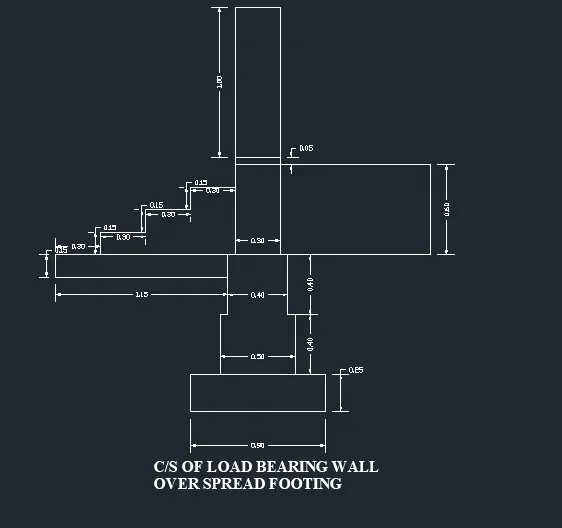
C1 : C.S OF LOAD BEARING WALL OVER SPREAD FOOTING
PROCEDURE :
- Open the auto cad, in command box type QNEW click on advance setup, imperial select the decimal and select the precision as a 0.00 and select the angle of direction of the drawing , orientation and the angle, the plot area.
- Create the rectangle by typing the REC in the command box.
- Specify the first starting point of the rectangle, click the dimension and specify the length of the rectangle as 0.9 and width of the rectangle as 0.25.
- Create the another rectangle by specifying the starting point of rectangle as 0.2 units away from the starting point of first rectangle.
- click the dimension and specify the length of the rectangle as 0.5 and width of the rectangle as 0.40.
- Create the another rectangle by specifying the starting point of rectangle as 0.05 units away from the top corner of second rectangle starting point of second rectangle.
- Click the dimension and specify the length of the rectangle as 0.4 and width of the rectangle as 0.40.
- Trim the bottom length of 3rd rectangle by using the trim command.
- Create the fourth rectangle by specifying the starting point is 0.05units away from the top corner of the 3rd rectangle. select the dimensions and give the length of the rectangle as 0.3 and width of rectangle as 0.6.
- Create the fifth rectangle by specifying the starting point is the top corner of the 4th rectangle. select the dimensions and give the length of the rectangle as 0.3 and width of rectangle as 0.05.
- Create the 6th rectangle by specifying the starting point is the top corner of the 5th rectangle. select the dimensions and give the length of the rectangle as 0.3 and width of rectangle as 1.
- Click on the line command select the starting point as top left side corner of the 3rd rectangle. select the ortho is on
- keep the cursor on negative x dirextion enter the length of the line as 1.15 units move the cursor downside enter the length 0.15 and move the cursor in positive x direction enter the length as 1.15 units.
- Select the line command specify the starting point of the line as 0.3 units in positive x direction from end point of first line.
- keep the cursor above enter 0.15 units and cursor in the right direction 0.3 units. keep the cursor above enter 0.15 units and cursor in the right direction 0.3 units. keep the cursor above enter 0.15 units and cursor in the right direction 0.3 units.
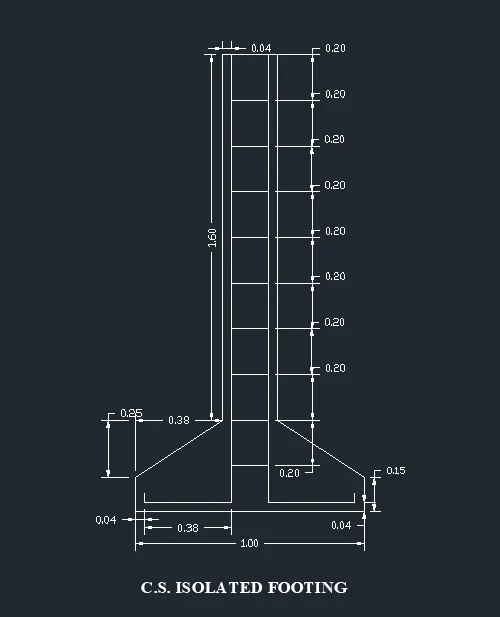
C2 : C.S. ISOLATED FOOTING
PROCEDURE :
- Open the auto cad, in command box type QNEW click on advance setup, imperial select the decimal and select the precision as a 0.00 and select the angle of direction of the drawing , orientation and the angle, the plot area.
- select the line command Specify the starting point of the line and ortho is on.
- Enter the length of the line as 1 units in positive x direction.
- Keep the cursor upward in y direction enter the length as 0.15 units.
- In the command box enter @-0.38, 0.25 from that point keep the cursor upward positive y direction enter the length of the line as 1.60 and keep the cursor in left side enter the length as 0.24.
- Keep the cursor downward enter the length as 1.16 units and in command box Enter the coordinates @-0.38,-0.25 and enter the close option in the command box.
- Select the line command specify the first point 0.04 units away form the top corner of the column. keep the cursor downward enter the length as 1.96 units.
- Select the offset option and object to be offset ie column main bar and give the offset distance as 0.16 units
- Enter O in the command box slect the top line of the coumn i.e 0.24 units enter offset distance as 0.2 in downward direction.
- Trim the excess line beyond the main bar by Entering Tr in command bar.
- select the offset the slect the object give the offset distance 0.2units in 8 numbers.
- The bottom surface of the line is offset at distance of 0.04 upward and trim excess line by using the commnd TR.
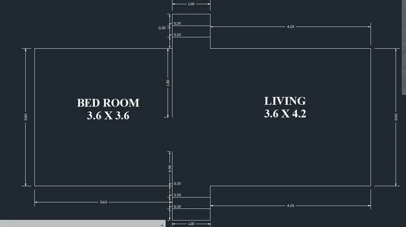
C3 : LINE DIAGRAM OF A TWO BEDROOM BUILDING
PROCEDURE :
- Open the auto cad, in command box type QNEW click on advance setup, imperial select the decimal and select the precision as a 0.00 and select the angle of direction of the drawing , orientation and the angle, the plot area.
- Select the polyline from the ribbon specify the first point of the polyline and the enter the length of the polyline as 0.90 units in the downward direction (-y axis).
- Enter the length of the polyline as 3.60 in -x direction ie left side and 3.6 units in upward and 3.6 units in the right side and last 1.80 units downward.
- Select the line command the starting point of the line is right corner of the bedroom and the length of the line as 0.9 units in upwards and 1 units right (+X axis) and downward 0.9 Units.
- Enter O from the command box select the object and give the offset distance as 0.3 units in two numbers.
- Select the polyline from the ribbon and specify the first point as right side of the steps and enter the length of 4.20 in +x direction and 3.6 in -y direction and 4.20 units in -x direction.
- Select the line command enter the length of the line as 0.9 units in -x direction and length of 1 units in left side and 0.9 units in upward.
- enter the O in the command box slect the object and give the offset distance as 0.30 units in upward direction in two times.
- Select the dimension from the ribbon and give the dimension of the the linea.
C4 : C.S OF LOAD BEARING WALL SHOWING FOUNDATION DETAILS
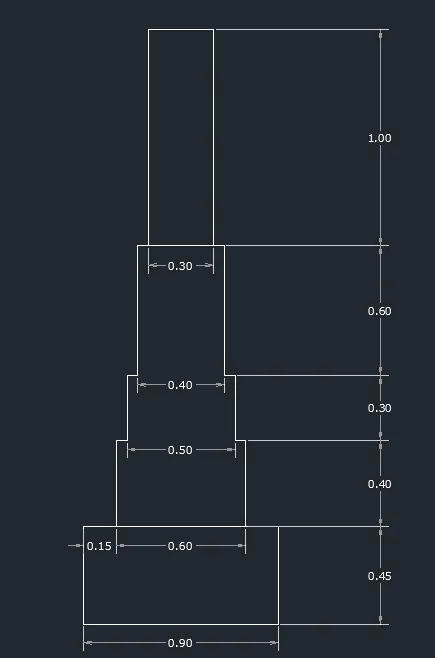
PROCEDURE :
- Open the auto cad, in command box type QNEW click on advance setup, imperial select the decimal and select the precision as a 0.00 and select the angle of direction of the drawing , orientation and the angle, the plot area.
- Create the rectangle by the command REC then specify the first starting point of the rectangle and select the dimension and give dimension of the rectangle such as length and width as 0.9 and 0.45.
- Select rectangle and choose the starting point as by Keeping the cursor point on top corner of the 1st rectangle (0.9 x 0.45) move towards positive x direction and enter the required distance as 0.05 that is the starting point of the next rectangle.
- Select the dimension and give the length as 0.9 and width as a 0.45 that the second rectangle is formed.
- Create rectangle by entering the command REC and choose the starting point as by Keeping the cursor point on top corner of the 2 nd rectangle (0.5 x 0.4) move towards positive x direction and enter the required distance as 0.15 that is the starting point of the next rectangle.
- Give diemention of the rectanglr as 0.5 length and 0.4 width.
- Like above procedure the the others rectangle are formed.
- Trim the line by using the command "TR" the bottom of the second and third rectangle.
- Select the dimension command and give the dimention of the all lines.
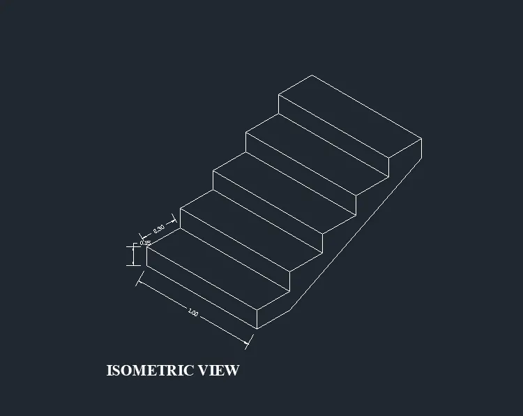
C5 : ISOMETRIC VIEW
PROCEDURE :
- Open the auto cad, in command box type QNEW click on advance setup and imperial, select the decimal and select the precision as a 0.00 and select the angle of direction of the drawing , orientation and the angle, plot area.
- Type the "DS" in the command box mark the isometric.
- make sure the ortho mode is on.
- From the isometric view select the isoplane left.
- Select the line command specify the starting point of the line. enter the length 1 units in -X axis
- Select the isoplane right select the polyline from the ribbon enter the 0.15 units in the +y axis and 0.30 units in +x axis.
- Enter 0.15 units in the +y axis and 0.30 +x axis, 0.15 units in the +y axis and 0.30 +x axis similarly upto two times.
- Copy the the poly line by using the command "CO" enter the base point.
- Copied polyline placed at the starting point of the first line.
- select the isoplane left. join the all riser and threads.
- click on the isoplane right and select the line command.
- specify the the first point from the starting point of the stair in the +x axis at the length of 0.3 units.
- draw the vertical distance of 0.15 units in downwards from the top point of the stair.
- Join these two points and the stair is drawn.
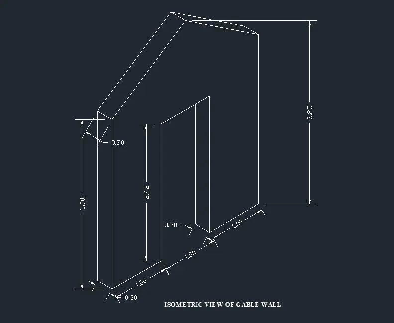
C6 : ISOMETRIC VIEW OF GABLE WALL
PROCEDURE :
- Open the auto cad, in command box type QNEW click on advance setup and imperial, select the decimal and select the precision as a 0.00 and select the angle of direction of the drawing , orientation and the angle, plot area.
- Type the "DS" in the command box mark the isometric snap.
- make sure the ortho mode is on.
- select the isoplane right and enter line command specify the starting point of the line.
- Give the length of the line 1 units by keeping the cursor in -x axis.
- Move the cursor to upwards enter the line length of 2.42 units and move the cursor to left side enter 1 units.
- Move the cursor downwards enter the length 2.42 units and move the cursor left side enter the length 1 units.
- move the cursor upwards and enter 3 units. and move cursor in right side by 3 units and close the figure.
- Select the isoplane left select the command L specify the first point as right corner opening and give 0.3 units in left side.
- select the isoplane right enter L join line.
- From the centre of the bottom line erect the line upward.
- from the first point of the move cursor upward at the distance of 3.25 units draw the horizontal line.
- Join the this intersection point with the line from the top points. erase the projection lines.
- select the isoplane left from the all the points enter the 0.3 units in -x axis and join all points by line command.