Drafting of various geometries using Chamfer, Fillet tool in AutoCad
Slide-1
Aim:
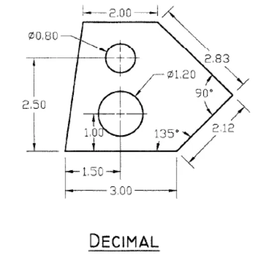
Draw the given geometry using decimal units.
Introduction:
The desired geometry picture is created in autocad by using : Line, Circle, Dimlin tools.
Procedure:
Step-1:-
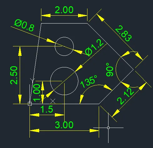
- Type the command "L" for the line and specify the coordinate for starting point (0,0).
- Specify the next point: @3.0<0
- Specify the next point: @2.12<45
- Specify the next point: @2.83<135
- Specify the next point: @2.0<0
- Enter "C" to close the next point at starting point.
Step-2:-
- Type the command "C" for the circle and specify the centre point of the circle (1.5,1.0).
- Specify the diameter of the circle: 0.12.
Step-3:-
- Type the command "C" for the circle and specify the coordinate for starting point (1.5,2.5).
- Specify the diameter of the circle: 0.12.
Step-4:-
- Type the command "Dimlin" to measure the dimensions of the objects.
- Specify the first and second extension line origin.
Result:
Slide-2
Aim:
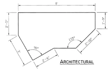
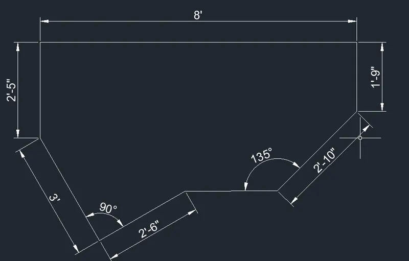
Draw the given geometry using architectural units.
Introduction:
The desired geometry picture is created in autocad by using : Line, Dimlin tools.
Procedure:
Step-1:-
- For the "Architectural" setup type "Dimstyle" in the dialouge box and press enter.
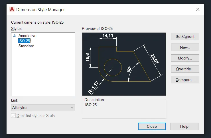
- select "modify" and in primary units tab choose unit format as Architectural and press OK.
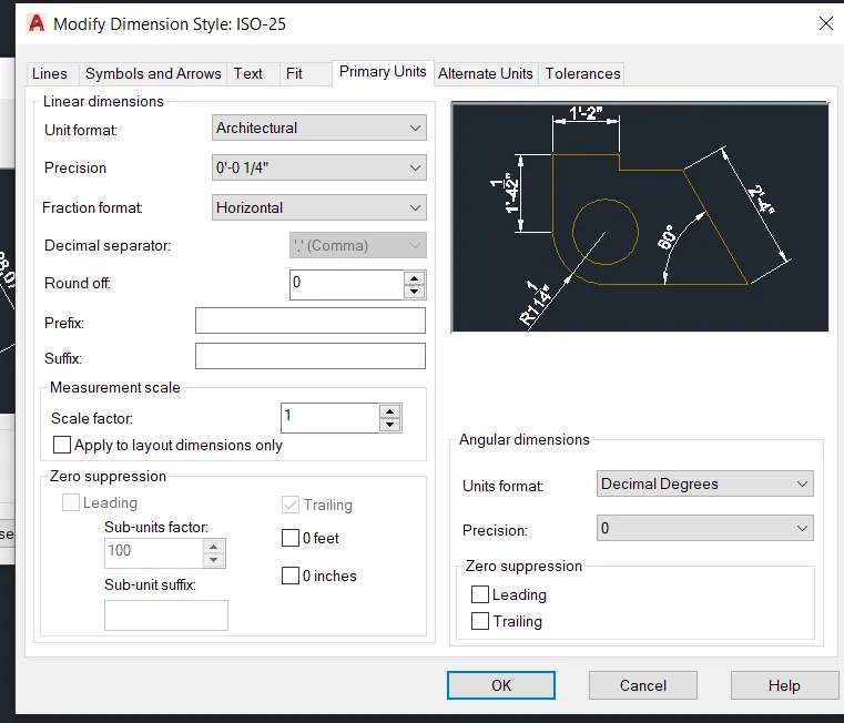
Step-2:-
- Type the command "L" for the line and specify the coordinate for starting point (0'-50",0'-50").
- Specify the next point: @2'-10"<45.
- Specify the next point: @1'-09"<90.
- Specify the next point: @8'-0"<180.
- Specify the next point: @2'-05"<270.
- Specify the next point: @3'-0"<300.
- Specify the next point: @2'-06"<30.
- Enter "C" to close the next point at starting point.
Step-3:-
- Type the command "Dimlin" to measure the dimensions of the objects.
- Specify the first and second extension line origin.
Result:
Slide-3
Aim:
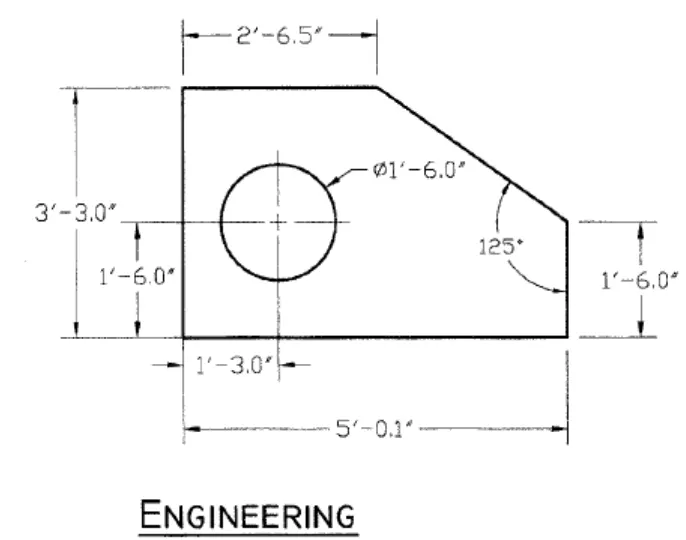
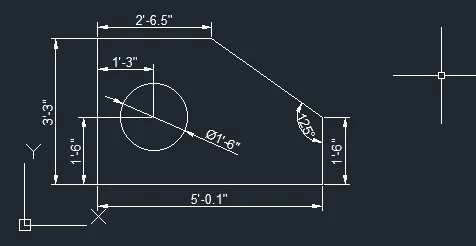
Draw the given geometry using engineering units.
Introduction:
The desired geometry picture is created in autocad by using : Line, Circle, Dimlin tools.
Procedure:
Step-1:-
- For the "Engineering" setup type "Dimstyle" in the dialouge box and press enter.
- Select "modify" and in primary units tab choose unit format as Engineering and press OK.
Step-2:-
- Type the command "L" for the line and specify the coordinate for starting point (0'-50",0'-50").
- Specify the next point: @2'-6.5"<180.
- Specify the next point: @3'-3.0"<270.
- Specify the next point: @5'-0.1"<0.
- Specify the next point: @1'-6.0"<90.
- Enter "C" to close the next point at starting point.
Step-3:-
- Type the command "C" for the circle and specify the centre point of the circle (2'-10.5",2'-5.0").
- Specify the diameter of the circle: 1'-6.0".
Step-4:-
- Type the command "Dimlin" to measure the dimensions of the objects.
- Specify the first and second extension line origin.
Result:
Slide-4
Aim:
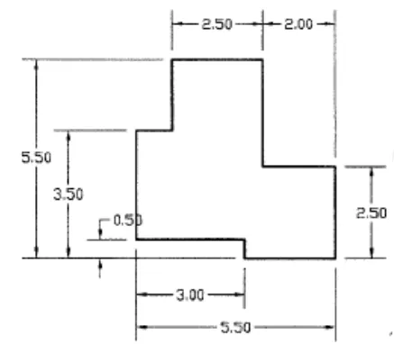
Draw the given geometrie using autocad tools.
Introduction:
The desired geometry picture is created in autocad by using : Line and Dimlin tools.
Procedure:
Step-1:-
- Type the command "L" for the line and specify the coordinate for starting point (0,0).
- Specify the next point: @3.0<0
- Specify the next point: @2.12<45
- Specify the next point: @2.83<135
- Specify the next point: @2.0<0
- Enter "C" to close the next point at starting point.
Step-2:-
- Type the command "Dimlin" to measure the dimensions of the objects.
- Specify the first and second extension line origin.
Result:
Slide-5
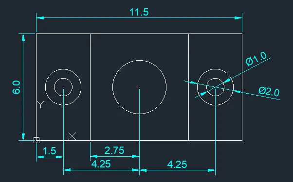
Aim:
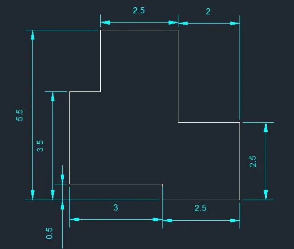
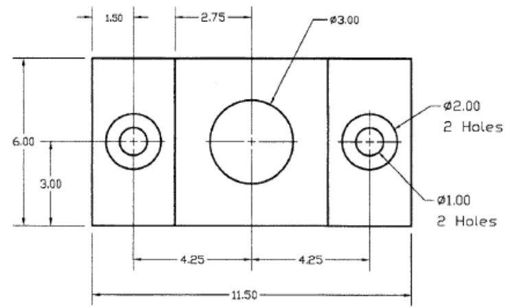
Draw the given geometry using autocad tools.
Introduction:
The desired geometry picture is created in autocad by using : Rectangle, Line, Circle, Mirror, and Dimlin tools.
Procedure:
Step-1:-
- Type the command "Rec" for the rectangle and specify the first corner point (0,0).
- Specify the other corner point: select dimension
- Specify the length of the rectangle: 11.50.
- Specify the width of the rectangle: 6.0.
Step-2:-
- Type the command "C" for the 1st circle and specify the centre point of the circle (1.5,3.0).
- Specify the diameter of the circle: 1.0.
- Type the command "C" for the 2nd circle and specify the centre point of the circle (1.5,3.0).
- Specify the diameter of the circle: 2.0.
Step-3:-
- Type the command "L" for the line and specify the first point (3,0).
- Specify the next point: @6<90.
Step-4:-
- Type the command "Mi" to mirror the object.
- Specify the objects: Select the line and circles.
- Specify first point of mirror line: Select the base mid point of the rectangle.
- Earse source object?: No.
Step-5:-
- Type the command "C" for the 1st circle and specify the centre point of the circle (5.75,3.0).
- Specify the diameter of the circle: 3.0.
Step-6:-
- Type the command "Dimlin" to measure the dimensions of the objects.
- Specify the first and second extension line origin.
Result:
Slide-6
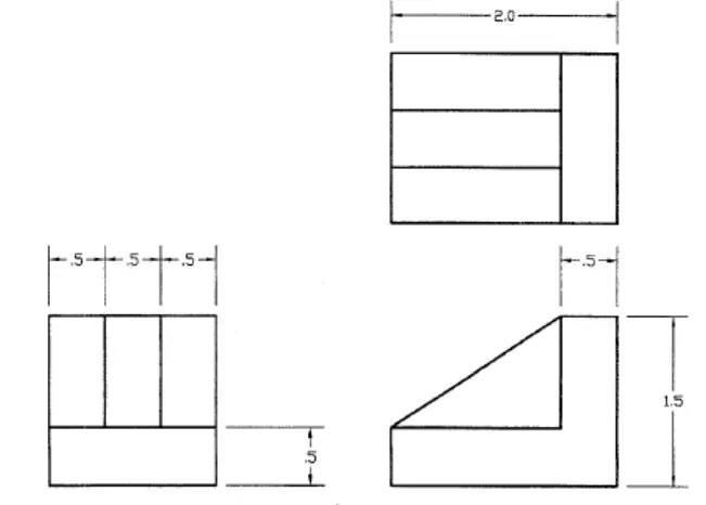
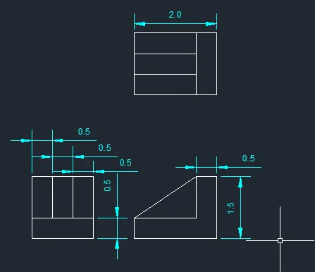
Aim:
Draw the given geometry using autocad tools.
Introduction:
The desired geometry picture is created in autocad by using : Rectangle, Line, and Dimlin tools.
Procedure:
Step-1:-
- Type the command "Rec" for the rectangle and specify the first corner point (10,10).
- Specify the other corner point: select dimension
- Specify the length of the rectangle: 2.0.
- Specify the width of the rectangle: 1.5.
Step-2:-
- Type the command "L" for the line and specify the first point (11.5,10).
- Specify the next point: @1.5<90.
- Type the command "L" for the line and specify the first point (10,10.5).
- Specify the next point: @1.5<0.
- Type the command "L" for the line and specify the first point (10,11).
- Specify the next point: @1.5<0.
Step-3:-
- Type the command "L" for the line and specify the first point (10,7).
- Specify the next point: @1.5<0.
- Specify the next point: @1.0<90.
- Specify the next point: @0.5<0.
- Specify the next point: @1.5<270.
- Specify the next point: @2.0<180.
- Specify the next point: @0.5<90.
- Enter "C" to close the next point at starting point.

Step-4:-
- Type the command "Rec" for the rectangle and specify the first corner point (7.5,6.5).
- Specify the other corner point: select dimension
- Specify the length of the rectangle: 1.5.
- Specify the width of the rectangle: 1.5.
Step-5:-
- Type the command "L" for the line and specify the first point (7.5,7).
- Specify the next point: @1.5<0.
- Type the command "L" for the line and specify the first point (8,7).
- Specify the next point: @1.0<0.
- Type the command "L" for the line and specify the first point (8.5,7).
- Specify the next point: @1.0<0.
Step-6:-
- Type the command "Dimlin" to measure the dimensions of the objects.
- Specify the first and second extension line origin.
Result:
Slide-7
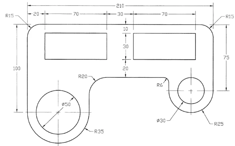
Aim:
Draw the given geometry using autocad tools.
Introduction:
The desired geometry picture is created in autocad by using : Rectangle, Line, Circle, Fillet, and Dimlin tools.
Procedure:
Step-1:-
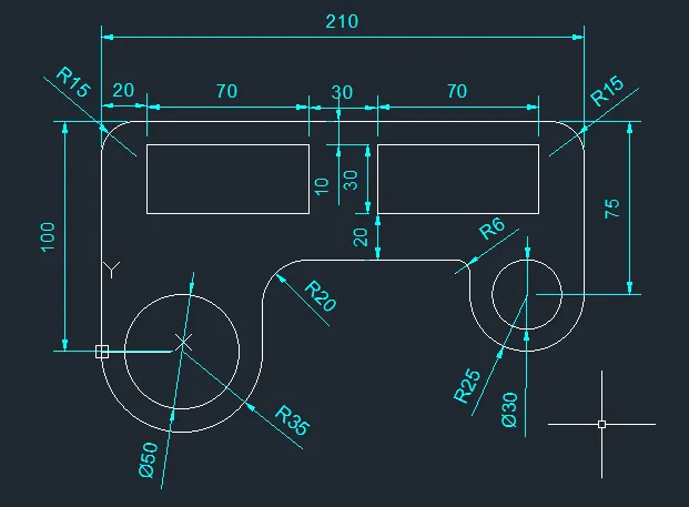
- Type the command "L" for the line and specify the first point (0,0).
- Specify the next point: @100<90.
- Specify the next point: @210<0.
- Specify the next point: @75<270.
Step-2:-
- Type the command "O" for the Offset some object.
- Specify offset distance: 60
- Select the object to offset: Select the 2nd line of the step-1.
- Specify point on side to offset: point move on in -ve Y-direction and click.
- Type E for exit.
Step-3:-
- Type the command "C" for the 1st circle and specify the centre point of the circle (35,0).
- Specify the radius of the circle: 35.
- Type the command "C" for the 2nd circle and specify the centre point of the circle (35,0).
- Specify the diameter of the circle: 50.
- Type the command "C" for the 3rd circle and specify the centre point of the circle (185,25).
- Specify the radus of the circle: 25.
- Type the command "C" for the 4th circle and specify the centre point of the circle (185,25).
- Specify the diameter of the circle: 30.
Step-4:-
- Type the command "L" for the line and specify the first point (70,0).
- Specify the next point: draw perpendicular to the offset line.
- Type the command "L" for the line and specify the first point (160,25).
- Specify the next point: draw perpendicular to the offset line.
Step-5:-
- Type the command "Rec" for the 1st rectangle and specify the first corner point (20,60).
- Specify the other corner point: select dimension
- Specify the length of the rectangle: 70.
- Specify the width of the rectangle: 30.
- Type the command "Rec" for the 2nd rectangle and specify the first corner point (120,60).
- Specify the other corner point: select dimension
- Specify the length of the rectangle: 70.
- Specify the width of the rectangle: 30.
Step-6:-
- Type the command "Tr" and press "double enter" to trim unwanted lines.

Step-7:-
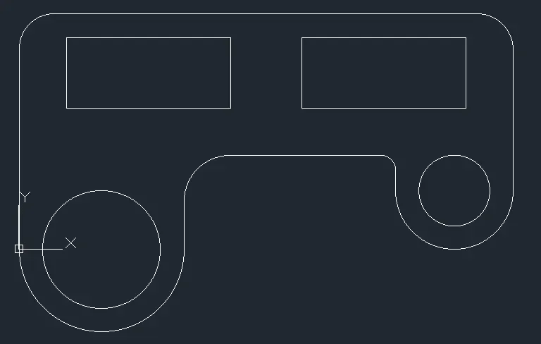
- Select fillet tool to round and fillets the edges of object.
- Select first object: select "radius"
- Specify fillet radius.
- Seect first object.
- Select second object.
Step-8:-
- Type the command "Dimlin" to measure the dimensions of the objects.
- Specify the first and second extension line origin.
Result:
Slide-8
Aim:
Draw the given geometry using autocad tools.
Introduction:
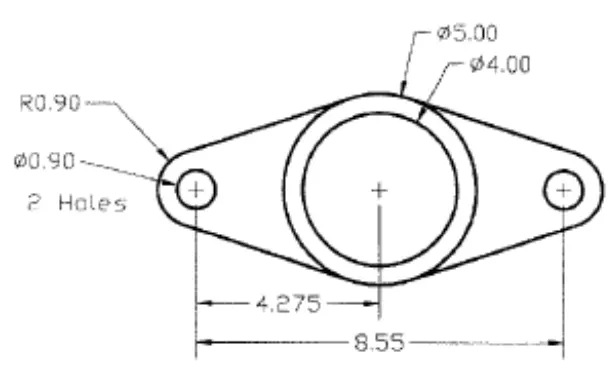
The desired geometry picture is created in autocad by using : Line, Circle, Fillet and Dimlin tools.
Procedure:
Step-1:-
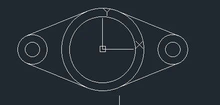
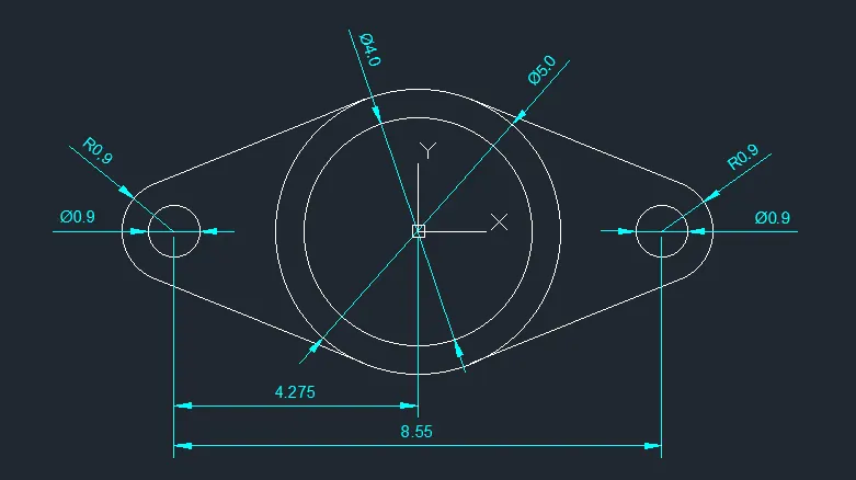
- Type the command "C" for the 1st circle and specify the centre point of the circle (0,0).
- Specify the diameter of the circle: 5.
- Type the command "C" for the 2nd circle and specify the centre point of the circle (0,0).
- Specify the diameter of the circle: 4.
- Type the command "C" for the 3rd circle and specify the centre point of the circle (-4.275,0).
- Specify the diameter of the circle: 0.9.
- Type the command "C" for the 4th circle and specify the centre point of the circle (4.275,0).
- Specify the radius of the circle: 0.9.
Step-2:-
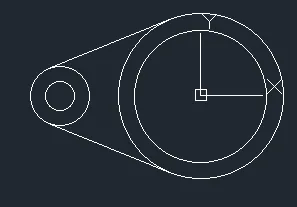
- Type the command "L" for the line.
- Specify first point: Tangent of 4th circle.
- Specify next point: join to the tangent of 1st circle.
Step-3:-
- Type the command "Mi" to mirror the object.
- Specify the objects: Select the line and circles.
- Specify first point of mirror line: Select the base mid point of the rectangle.
- Earse source object?: No.
Step-4:-
- Type the command "Tr" and press "double enter" to trim unwanted lines.
Step-5:-
- Type the command "Dimlin" to measure the dimensions of the objects.
- Specify the first and second extension line origin.
Result:
Slide-9
Aim:
Draw the given geometry using autocad tools.
Introduction:
The desired geometry picture is created in autocad by using : Circle, Fillet, Trim and Dimlin tools.
Procedure:
Step-1:-
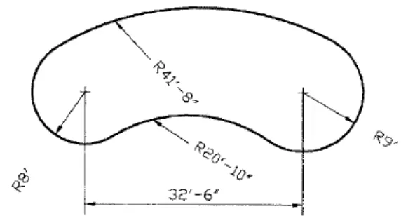
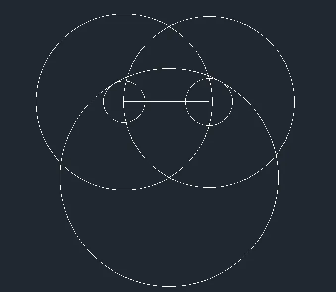
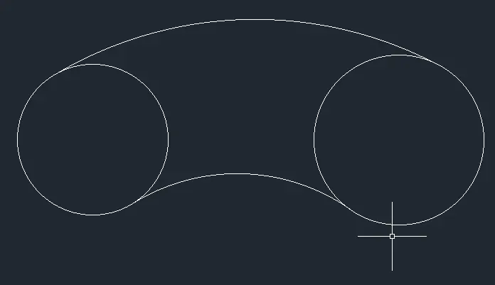
- Type the command "C" for the 1st circle and specify the centre point of the circle (10',10').
- Specify the radius of the circle: 8'.
- Type the command "C" for the 2nd circle and specify the centre point of the circle (42'-6",10').
- Specify the radius of the circle: 9'.
- Type the command "C" for the 3rd circle and specify the centre point of the circle (10',10').
- Specify the diameter of the circle: 33'-8".
- Type the command "C" for the 4th circle and specify the centre point of the circle (42'-6",10').
- Specify the radius of the circle: 32'-8".
- Type the command "C" for the 4th circle and specify the centre point of the circle : Bottom intersection of 3rd & 4th circle.
- Specify the radius of the circle: 41'-8".
Step-2:-
- Type the command "Tr" and press "double enter" to trim unwanted lines.

Step-3:-
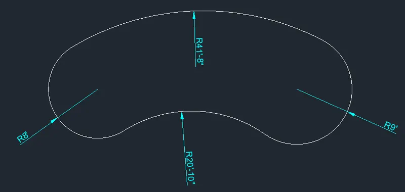
- Select fillet tool to round and fillets the edges of object.
- Select first object: select "radius"
- Specify fillet radius: 20'-10"
- Select first object: 1st circle
- Select second object: 2nd circle
Step-4:-
- Type the command "Dimlin" to measure the dimensions of the objects.
- Specify the first and second extension line origin.
Result:
Slide-10
Aim:
Draw the given geometry using autocad tools.
Introduction:
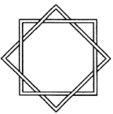
The desired geometry picture is created in autocad by using : Rectangle, Offset, Trim and Dimlin tools.
Procedure:
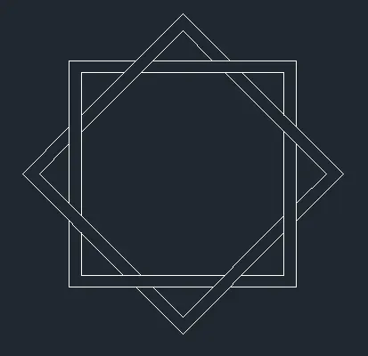
Step-1:-
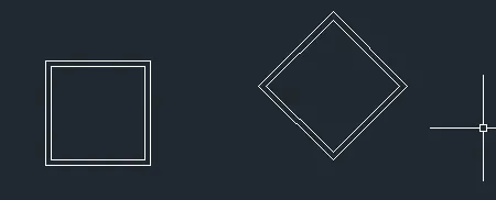
- Type the command "Rec" for the 1st rectangle and specify the first corner point (10,10).
- Specify the other corner point: select dimension
- Specify the length of the rectangle: 5.0.
- Specify the width of the rectangle: 5.0.
- Type the command "Rec" for the 2st rectangle and specify the first corner point (20,10).
- Specify the other corner point: select rotation
- Specify rotation angle: 45
- Specify the other corner point: select dimension
- Specify the length of the rectangle: 5.0.
- Specify the width of the rectangle: 5.0.
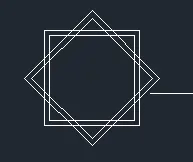
Step-2:-
- Type the command "O" to offset the rectangles.
- Specify offset distance
- Select the object to offset: choose the rectangles.
- Specify point on side to offset.
- Type "E" for exit.
Step-3:-
- Type the command "M" to move the object.
- Select objects: select the 2nd rectangle with its offset rectangle.
- Specify base point: Select its geometric central point of its own.
- Specify 2nd point: select 1st rectangle's geometric central point.
Step-4:-
- Type the command "Tr" and press "double enter" to trim unwanted lines.
Result:
Slide-11
Aim:
Draw the given geometry using autocad tools.
Introduction:
The desired geometry picture is created in autocad by using : Circle, Fillet, Trim and Dimlin tools.
Procedure:
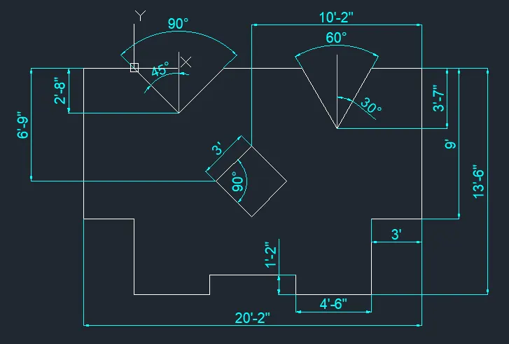
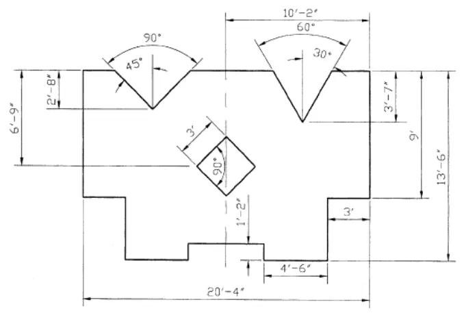
Step-1:-
- Type the command "L" for the line and specify the first point (0,0).
- Specify the next point: @-3'<180.
- Specify the next point: @-9'<270.
- Specify the next point: @3'<0.
- Specify the next point: @4'-6"<270.
- Specify the next point: @4'-6"<0.
- Specify the next point: @1'-2"<90.
- Specify the next point: @5'-2"<0.
- Specify the next point: @1'2"<270.
- Specify the next point: @4'-6"<0.
- Specify the next point: @4'-6"<90.
- Specify the next point: @3'<0.
- Specify the next point: @9'<90.
- Specify the next point: @-3'<180.
Step-2:-
- Type the command "L" for the line and specify the first point (-3',-2'-8").
- Specify the next point: @20'-4"<0.
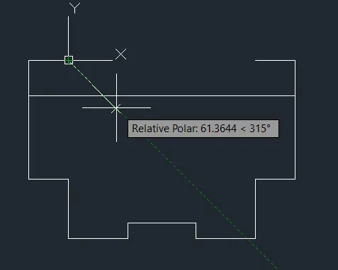
- Again type the command "L" for the line with polar tracking (45,90,135,180) and specify the first point at stating point of we start in step-1.
- Specify the next point: intersect to the above line shown like below:
- Again type the command "L" for the line with polar tracking (30,60,90,120,150,180) and specify the first point at ending point of we start in step-1.
- Specify the next point: intersect to the above line (like the top figure)
Step-3:-
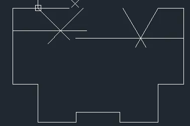
- Type the command "Mi" to mirror the object.
- Specify the objects: Select the line (polar lines made in step-2).
- Specify first point of mirror line: Select the intersection point of the base line and polar line.
- Earse source object?: No.
Step-4:-
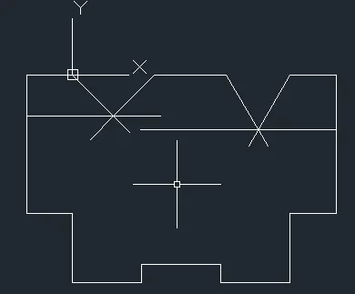
- Type the command "L" for the joining the line of top.
Step-5:-
- Type the command "Rec" for the 1st rectangle and specify the first corner point.
- Specify the other corner point: select Rotation
- Specify rotation angle: 45
- Specify the other corner point: select dimension
- Specify the length of the rectangle: 3'-0".
- Specify the width of the rectangle: 3'-0".
Step-6:-
- Type the command "M" to move the object.
- Select objects: select the rectangle.
- Specify base point.
- Specify 2nd point.
Step-7:-
- Type the command "Tr" and press "double enter" to trim unwanted lines.
Step-8:-
- Type the command "Dimlin" to measure the dimensions of the objects.
- Specify the first and second extension line origin.
Result: