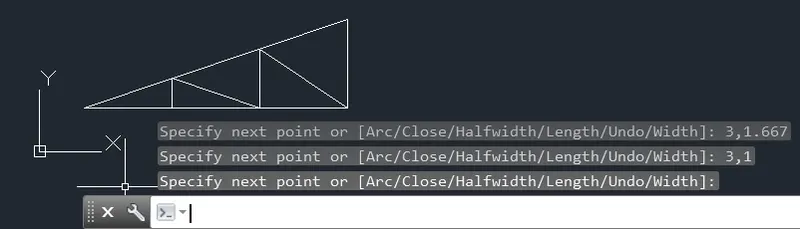
Creation of geometries by Coordinate system methods using AutoCad
1)P1:-
Aim:-
- Create the geometries of P1 drawing using all the coordinates system methods.
Introduction:-
There are four co-ordinate system in AutoCAD.
- Absolute Co-odinate system:-
- Absolute coordinates is distance or angle of axes relative to the origin of the coordinates. Absolute coordinate entry is the default. When drawing lines, AutoCAD is ready to place the next vertex wherever you tell it to go.
- Relative Co-odinate system:-
- A)Relative rectangular co-ordinates:- In this the distance or angle of axes relative to the last point. Remember to add @ before entering coordinate values, take @2, 3 for example, it shows the distance from the last point in the X-axis direction is 3 and in the Y-axis direction is 3.
- B)Relative Polar Co-odinate:- Polar coordinates are named for their “pole”; the reference point to start counting from, which is similar in concept to the origin. Polar coordinates employ one radial distance and one angle (by convention, the angle is measured counterclockwise from the x-axis). The angle signifies the direction, and the distance is how far to go in that direction from the pole.Polar coordinates in AutoCAD are given as R<Degrees, where:
- “R” is the radial distance
- “<” is the less than sign (but in this case represents the angle)
- “Degrees” is the value of the angle in degrees
- Direct distance entry:- This is the simple method of drawing. With direct distance entry, we can quickly specify a point relative to the last point you entered. At any prompt for a point location, move the cursor first to specify the direction, and then enter a numeric distance.
Procedure:-
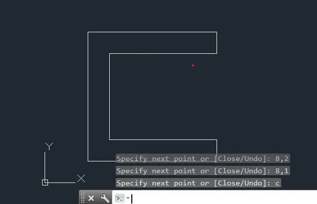
1)Absolute Co-ordinate system:-
- On opening the AutoCAD software, setup the units to imperial template and decimal system to 0.00. Set the limits in the command tab using 'Limits' before drafting.
- Steps:-
- Type the command 'L' for the line and specify the coordinate for starting point (2,1).
- Specify the next point: 2,7
- Specify the next point: 8,7
- Specify the next point: 8,6
- Specify the next point: 3,6
- Specify the next point: 3,2
- Specify the next point: 8,2
- Specify the next point: 8,1
- Enter 'C' to close the next point at starting point.
Result:-
2) Relative rectangular Co-ordinate system:-
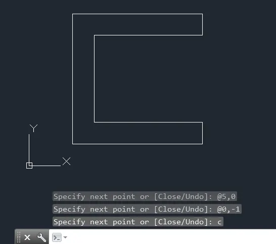
- Steps:-
- Type the command 'L' for the line and specify the coordinate for starting point (2,1).
- Specify the next point: @0,6
- Specify the next point: @6,0
- Specify the next point: @0,-1
- Specify the next point: @-5,0
- Specify the next point: @0,-4
- Specify the next point: @5,0
- Specify the next point: @0,-1
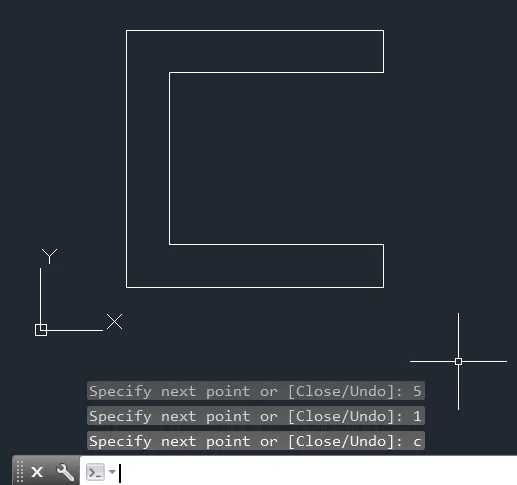
- Enter 'C' to close the next point at starting point.
Result:-
3)Relative polar Co-ordinate system:-
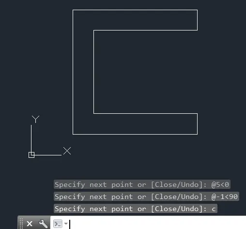
- Steps:-
- Type the command 'L' for the line and specify the coordinate for starting point (2,1).
- Specify the next point: @6<90
- Specify the next point: @6<0
- Specify the next point: @-1<90
- Specify the next point: @-5<0
- Specify the next point: @-4<90
- Specify the next point: @5<0
- Specify the next point: @-1<90
- Enter 'C' to close the next point at starting point.
Result:-
4)Direct distance entry:-
- Steps:-
- Type the command 'L' for the line and specify the coordinate for starting point (2,1).
- Type the length 6 in command box to +ve y-axis for next point.
- Type the length 6 in command box to +ve x-axis for next point.
- Type the length 1 in command box to -ve y-axis for next point.
- Type the length 5 in command box to -ve x-axis for next point.
- Type the length 4 in command box to -ve x-axis for next point.
- Type the length 5 in command box to +ve x-axis for next point.
- Type the length 1 in command box to -ve y-axis for next point.
- Enter 'C' to close the next point at starting point.
Result:-
2)P2:-
Aim:-
- Create the geometries of P2 drawing using all the coordinates system methods.
Introduction:-
There are four co-ordinate system in AutoCAD.
- Absolute Co-odinate system:-
- Absolute coordinates is distance or angle of axes relative to the origin of the coordinates. Absolute coordinate entry is the default. When drawing lines, AutoCAD is ready to place the next vertex wherever you tell it to go.
- Relative Co-odinate system:-
- A)Relative rectangular co-ordinates:- In this the distance or angle of axes relative to the last point. Remember to add @ before entering coordinate values, take @2, 3 for example, it shows the distance from the last point in the X-axis direction is 3 and in the Y-axis direction is 3.
- B)Relative Polar Co-odinate:- Polar coordinates are named for their “pole”; the reference point to start counting from, which is similar in concept to the origin. Polar coordinates employ one radial distance and one angle (by convention, the angle is measured counterclockwise from the x-axis). The angle signifies the direction, and the distance is how far to go in that direction from the pole.Polar coordinates in AutoCAD are given as R<Degrees, where:
- “R” is the radial distance
- “<” is the less than sign (but in this case represents the angle)
- “Degrees” is the value of the angle in degrees
- Direct distance entry:- This is the simple method of drawing. With direct distance entry, we can quickly specify a point relative to the last point you entered. At any prompt for a point location, move the cursor first to specify the direction, and then enter a numeric distance.
Procedure:-
1)Absolute Co-ordinate system:-
- On opening the AutoCAD software, setup the units to imperial template and decimal system to 0.00. Set the limits in the command tab using 'Limits' before drafting.
- Steps:-
- Type the command 'L' for the line and specify the coordinate for starting point (2,1).
- Specify the next point: 5,1
- Specify the next point: 5,5
- Specify the next point: 6,5
- Specify the next point: 6,1
- Specify the next point: 9,1
- Specify the next point: 7,8
- Specify the next point: 4,8
- Enter 'C' to close the next point at starting point.
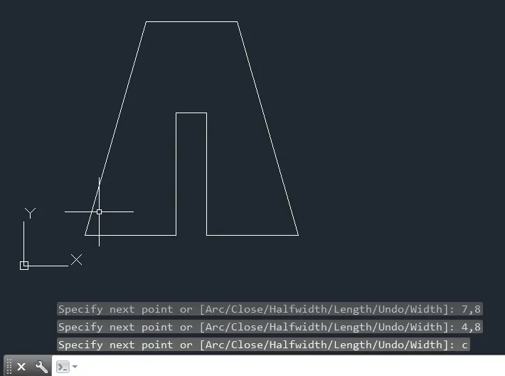
2) Relative rectangular Co-ordinate system:-
- Steps:-
- Type the command 'L' for the line and specify the coordinate for starting point (2,1).
- Specify the next point: @3,0
- Specify the next point: @0,4
- Specify the next point: @1,0
- Specify the next point: @0,-4
- Specify the next point: @3,0
- Specify the next point: @-2,7
- Specify the next point: @-3,0
- Enter 'C' to close the next point at starting point.
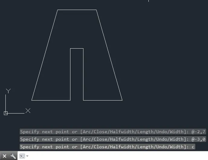
3)Relative polar Co-ordinate system:-
- Steps:-
- Type the command 'L' for the line and specify the coordinate for starting point (2,1).
- Specify the next point: @3<0
- Specify the next point: @4<90
- Specify the next point: @1<360
- Specify the next point: @4<270
- Specify the next point: @3<0
- Specify the next point: @7<90
- Specify the next point: @2<180
- Specify the next point: @3<180
- Enter 'C' to close the next point at starting point.
- Then delete the line command no: 7 & 8 [i.e: @7<90 & @2<180] and join the line command no 6 & 9 [i.e: @3<180 & @3<0].
Result:-
4)Direct distance entry:-
- Steps:-
- Type the command 'L' for the line and specify the coordinate for starting point (2,1).
- Type the length 3 in command box to +ve x-axis for next point.
- Type the length 4 in command box to +ve y-axis for next point.
- Type the length 1 in command box to -ve x-axis for next point.
- Type the length 4 in command box to -ve y-axis for next point.
- Type the length 3 in command box to +ve x-axis for next point.
- Type the length 7 in command box to +ve y-axis for next point.
- Type the length 2 in command box to -ve y-axis for next point.
- Type the length 3 in command box to -ve y-axis for next point.
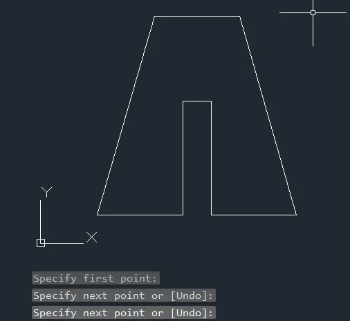
- Enter 'C' to close the next point at starting point.
- Then delete the line command no: 7 & 8 and join the line command no 6 & 9 [i.e: @3<180 & @3<0].
Result:-
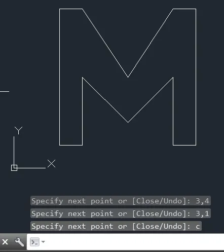
3)P4:-
Aim:-
- Create the geometries of P4 drawing using any coordinates system methods.
Introduction:-
There are four co-ordinate system in AutoCAD. Here I have been using the absolute coordinate system to draw the P4 picture.
- Absolute Co-odinate system:- Absolute coordinates is distance or angle of axes relative to the origin of the coordinates. Absolute coordinate entry is the default. When drawing lines, AutoCAD is ready to place the next vertex wherever you tell it to go.
Procedure:-
- On opening the AutoCAD software, setup the units to imperial template and decimal system to 0.00. Set the limits in the command tab using 'Limits' before drafting.
- Steps:-
- Type the command 'L' for the line and specify the coordinate for starting point (2,1).
- Specify the next point: 2,8
- Specify the next point: 3,8
- Specify the next point: 5,4
- Specify the next point: 7,8
- Specify the next point: 8,8
- Specify the next point: 8,1
- Specify the next point: 7,1
- Specify the next point: 7,4
- Specify the next point: 5,2
- Specify the next point: 3,4
- Specify the next point: 3,1
- Enter 'C' to close the next point at starting point.
Result:-
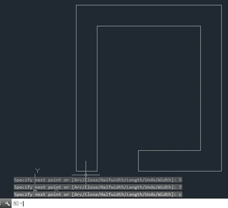
4)P5:-
Aim:-
- Create the geometries of P5 drawing using any coordinates system methods.
Introduction:-
There are four co-ordinate system in AutoCAD. Here I have been using the direct distance entry method to draw the P5 picture.
- Direct distance entry:- This is the simple method of drawing. With direct distance entry, we can quickly specify a point relative to the last point you entered. At any prompt for a point location, move the cursor first to specify the direction, and then enter a numeric distance.
Direct distance entry:-
- Steps:-
- Type the command 'L' for the line and specify the coordinate for starting point (2,1).
- Type the length 8 in command box to +ve y-axis for next point.
- Type the length 7 in command box to +ve x-axis for next point.
- Type the length 8 in command box to -ve y-axis for next point.
- Type the length 4 in command box to -ve x-axis for next point.
- Type the length 1 in command box to +ve y-axis for next point.
- Type the length 3 in command box to +ve x-axis for next point.
- Type the length 6 in command box to +ve y-axis for next point.
- Type the length 5 in command box to -ve x-axis for next point.
- Type the length 7 in command box to -ve y-axis for next point.
- Enter 'C' to close the next point at starting point.
Result:-
5)P7:-
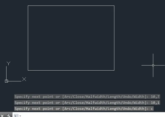
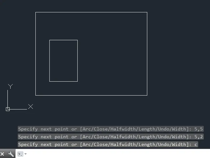
Aim:-
- Create the geometries of P7 drawing using any coordinates system methods.
Introduction:-
There are four co-ordinate system in AutoCAD. Here I have been using the absolute coordinate system to draw the P7 picture.
- Absolute Co-odinate system:- Absolute coordinates is distance or angle of axes relative to the origin of the coordinates. Absolute coordinate entry is the default. When drawing lines, AutoCAD is ready to place the next vertex wherever you tell it to go.
Procedure:-
- On opening the AutoCAD software, setup the units to imperial template and decimal system to 0.00. Set the limits in the command tab using 'Limits' before drafting.
Steps:-
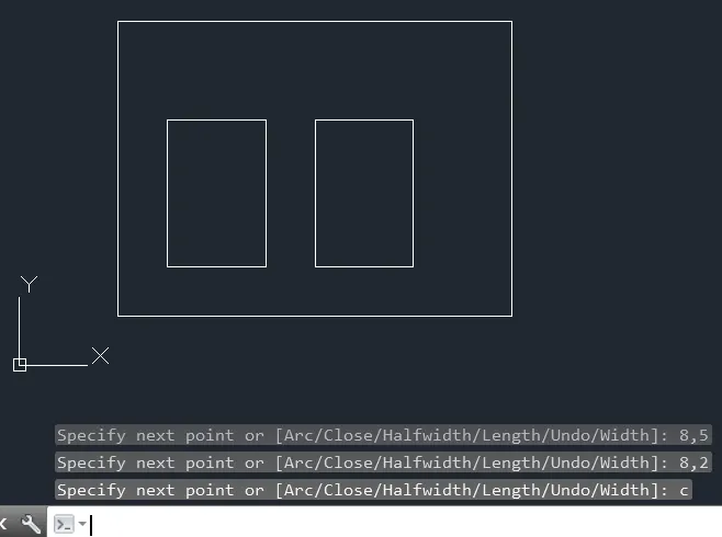
i)
- Type the command 'L' for the line and specify the coordinate for starting point (2,1).
- Specify the next point: 2,7
- Specify the next point: 10,7
- Specify the next point: 10,1
- Enter 'C' to close the next point at starting point.
ii)
- Type the command 'L' for the line and specify the coordinate for starting point (3,2).
- Specify the next point: 3,5
- Specify the next point: 5,5
- Specify the next point: 5,2
- Enter 'C' to close the next point at starting point.
iii)
- Type the command 'L' for the line and specify the coordinate for starting point (6,2).
- Specify the next point: 6,5
- Specify the next point: 8,5
- Specify the next point: 8,2
- Enter 'C' to close the next point at starting point.
Result:-
i)
ii)
iii)
6)P8:-
Aim:-
- Create the geometries of P8 drawing using any coordinates system methods.
Introduction:-
There are four co-ordinate system in AutoCAD. Here I have been using the relative rectangular coordinate system to draw the P8 picture.
- Relative Co-odinate system:-
- A)Relative rectangular co-ordinates:- In this the distance or angle of axes relative to the last point. Remember to add @ before entering coordinate values, take @2, 3 for example, it shows the distance from the last point in the X-axis direction is 3 and in the Y-axis direction is 3.
Procedure:-
- Steps:-
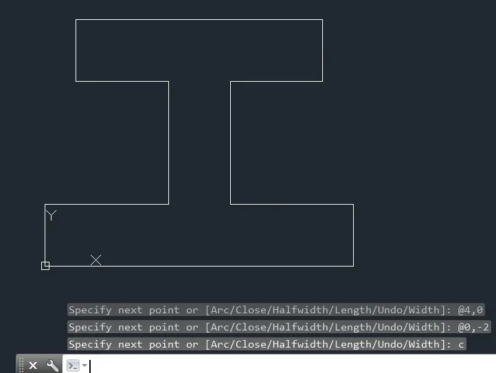
- Type the command 'L' for the line and specify the coordinate for starting point (0,0).
- Specify the next point: @0,2
- Specify the next point: @4,0
- Specify the next point: @0,4
- Specify the next point: @-3,0
- Specify the next point: @0,2
- Specify the next point: @8,0
- Specify the next point: @0,-2
- Specify the next point: @-3,0
- Specify the next point: @0,-4
- Specify the next point: @4,0
- Specify the next point: @0,-2
- Enter 'C' to close the next point at starting point.
Result:-
7)P9:-
Aim:-
- Create the geometries of P9 drawing using any coordinates system methods.
Introduction:-
There are four co-ordinate system in AutoCAD. Here I have been using the absolute coordinate system to draw the P9 picture.
- Absolute Co-odinate system:- Absolute coordinates is distance or angle of axes relative to the origin of the coordinates. Absolute coordinate entry is the default. When drawing lines, AutoCAD is ready to place the next vertex wherever you tell it to go.
Procedure:-
- On opening the AutoCAD software, setup the units to imperial template and decimal system to 0.00. Set the limits in the command tab using 'Limits' before drafting.
- Steps:-
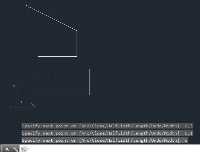
- Type the command 'L' for the line and specify the coordinate for starting point (1,1).
- Specify the next point: 1,8
- Specify the next point: 5,6
- Specify the next point: 5,4
- Specify the next point: 2,4
- Specify the next point: 2,2
- Specify the next point: 3,2
- Specify the next point: 3,3
- Specify the next point: 6,3
- Specify the next point: 6,1
- Enter 'C' to close the next point at starting point.
Result:-
8)P10:-
Aim:-
- Create the geometries of P10 drawing using any coordinates system methods.
Introduction:-
There are four co-ordinate system in AutoCAD. Here I have been using the absolute coordinate system to draw the P10 picture.
- Absolute Co-odinate system:- Absolute coordinates is distance or angle of axes relative to the origin of the coordinates. Absolute coordinate entry is the default. When drawing lines, AutoCAD is ready to place the next vertex wherever you tell it to go.
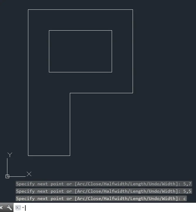
Procedure:-
- On opening the AutoCAD software, setup the units to imperial template and decimal system to 0.00. Set the limits in the command tab using 'Limits' before drafting.
Steps:-
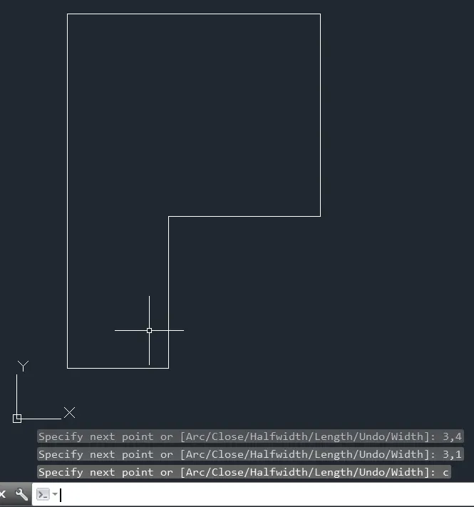
i)
- Type the command 'L' for the line and specify the coordinate for starting point (1,1).
- Specify the next point: 1,8
- Specify the next point: 6,8
- Specify the next point: 6,4
- Specify the next point: 3,4
- Specify the next point: 3,1
- Enter 'C' to close the next point at starting point.
ii)
- Type the command 'L' for the line and specify the coordinate for starting point (2,5).
- Specify the next point: 2,7
- Specify the next point: 5,7
- Specify the next point: 5,5
- Enter 'C' to close the next point at starting point.
Result:-
i)
ii)
9)Profile Wood [P11]:-
Aim:-
- Create the geometries of Profile Wood [P11] drawing using any coordinates system methods.
Introduction:-
There are four co-ordinate system in AutoCAD. Here I have been using the absolute coordinate system to draw the Profile Wood [P11] picture.
- Absolute Co-odinate system:- Absolute coordinates is distance or angle of axes relative to the origin of the coordinates. Absolute coordinate entry is the default. When drawing lines, AutoCAD is ready to place the next vertex wherever you tell it to go.
Procedure:-
- On opening the AutoCAD software, setup the units to imperial template and decimal system to 0.00. Set the limits in the command tab using 'Limits' before drafting.
Steps:-
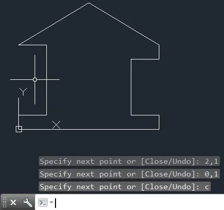
i)
- Type the command 'L' for the line and specify the coordinate for starting point (0,0).
- Specify the next point: 10,0
- Specify the next point: 10,1
- Specify the next point: 8,1
- Specify the next point: 8,5
- Specify the next point: 10,5
- Specify the next point: 10,6
- Specify the next point: 5,9
- Specify the next point: 0,6
- Specify the next point: 2,6
- Specify the next point: 2,1
- Specify the next point: 0,1
- Enter 'C' to close the next point at starting point.
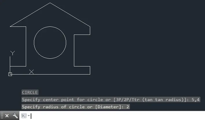
ii)
- Type the command 'c' for the circle and specify the coordinate for starting point (5,4).
- Specify the radius of the circle: 2.
Result:-
i)
ii)
10)Queen Post Truss [P12]:-
Aim:-
- Create the geometries of Queen Post Truss[P12] drawing using any coordinates system methods.
Introduction:-
There are four co-ordinate system in AutoCAD. Here I have been using the absolute coordinate system to draw the Queen Post Truss[P12] picture.
- Absolute Co-odinate system:- Absolute coordinates is distance or angle of axes relative to the origin of the coordinates. Absolute coordinate entry is the default. When drawing lines, AutoCAD is ready to place the next vertex wherever you tell it to go.
Procedure:-
- On opening the AutoCAD software, setup the units to imperial template and decimal system to 0.00. Set the limits in the command tab using 'Limits' before drafting.
Steps:-
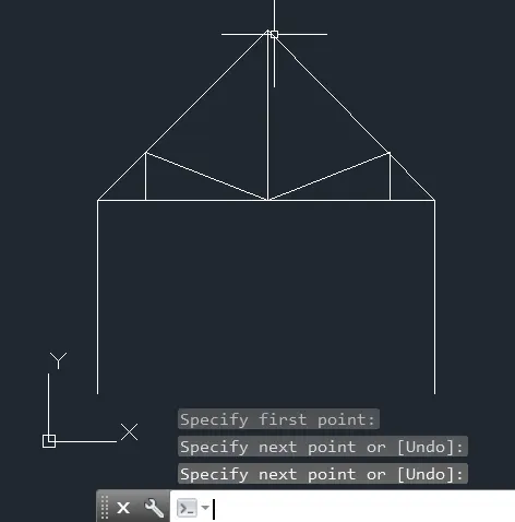
i)
- Type the command 'L' for the line and specify the coordinate for starting point (1,1).
- Specify the next point: 1,5
- Specify the next point: 8,5
- Specify the next point: 8,1
- Press double enter in command box to stop.
ii)
- Type the command 'L' for the line and specify the coordinate for starting point (1,5).
- Specify the next point: 4.536,8.536
- Specify the next point: 8,5
- Press double enter in command box to stop.
iii)
- Type the command 'L' for the line and specify the coordinate for starting point (2,5).
- Specify the next point: 2,6
- Specify the next point: 4.536,5
- Specify the next point: 7.072,6
- Specify the next point: 7.072,5
- Press double enter in command box to stop.
iv)
- Type the command 'L' for the line and specify the coordinate for starting point (4.536,5).
- Specify the next point: 8.536,4.536
- Press double enter in command box to stop.
Result:-
11)Mono Pitch [P13]:-
Aim:-
- Create the geometries of Mono Post[P13] drawing using any coordinates system methods.
Introduction:-
There are four co-ordinate system in AutoCAD. Here I have been using the absolute coordinate system to draw the Mono Post[P13] picture.
- Absolute Co-odinate system:- Absolute coordinates is distance or angle of axes relative to the origin of the coordinates. Absolute coordinate entry is the default. When drawing lines, AutoCAD is ready to place the next vertex wherever you tell it to go.
Procedure:-
- On opening the AutoCAD software, setup the units to imperial template and decimal system to 0.00. Set the limits in the command tab using 'Limits' before drafting.
Steps:-
i)
- Type the command 'L' for the line and specify the coordinate for starting point (7,3).
- Specify the next point: 1,1
- Specify the next point: 7,1
- Enter 'C' to close the next point at starting point.
ii)
- Type the command 'L' for the line and specify the coordinate for starting point (7,1).
- Specify the next point: 5,2.333
- Specify the next point: 5,1
- Specify the next point: 3,1.667
- Specify the next point: 3,1
- Enter 'C' to close the next point at starting point.
Result:-