Creating a Floor plan, Footing detail and Isometric view using AutoCad
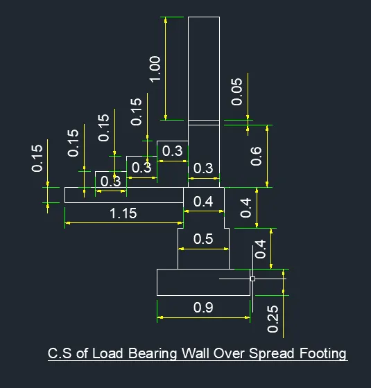
1:Load Bearing wall over spread footing
A) Aim:-
To draw a figure C1 of Load Bearing wall over spread footing.
B)Introduction:-
The purpose of Load Bearing Wall is to take loads from the beams,columns, and slab and transfer the load to the foundation. To draw this figure (Load Bearing wall over spread footing) used command are:- Line, Polyline, Rectangle, Offset, Trim and Dimlinear.
C)Procedure:-
Step-1:-
- Type the command "Rec" to draw the rectangles.
- Specify first corner point: 3,3
- Specify other corner point: enter "d" [Or select Dimension]
- Specify length for rectangle: 0.9
- Specify width for rectangle: 0.25
- Specify other corner point: click cursor in Y-direction.
Step-2:-
- Type the command "Rec" to draw the rectangles.
- Specify first corner point: 3.20,3.25
- Specify other corner point: enter "d" [Or select Dimension]
- Specify length for rectangle: 0.5
- Specify width for rectangle: 0.4
- Specify other corner point: click cursor in Y-direction.
Step-3:-
- Type the command "Rec" to draw the rectangles.
- Specify first corner point: 3.25,3.65
- Specify other corner point: enter "d" [Or select Dimension]
- Specify length for rectangle: 0.4
- Specify width for rectangle: 0.4
- Specify other corner point: click cursor in Y-direction.
Step-4:-
- Type the command "Rec" to draw the rectangles.
- Specify first corner point: 3.25,3.90
- Specify other corner point: enter "d" [Or select Dimension]
- Specify length for rectangle: -1.15
- Specify width for rectangle: 0.15
- Specify other corner point: click cursor in Y-direction.
Step-5:-
- Type the command "Rec" to draw the rectangles.
- Specify first corner point: 3.30,4.05
- Specify other corner point: enter "d" [Or select Dimension]
- Specify length for rectangle: 0.3
- Specify width for rectangle: 1.65
- Specify other corner point: click cursor in Y-direction.
Step-6:-
- Type the command "L" to draw the lines.
- Specify first point: 3.3,4.65
- Specify next point: 3.6,4.65
- Press "Esc" for close the command.
Step-7:-
- Type the command "O" to offset some object.
- Specify offset distance: 0.05
- Select the object to offset: Select the line used in the privious step.
- Specify point on side to offset: point move in y-direction and click.
- Type "E" for exit.
Step-8:-
- Type the command "Pl" to draw the polylines.
- Specify start point: 2.4,4.05
- Specify next point: @0,0.15
- Specify next point: @0.3,0
- Specify next point: @0,0.15
- Specify next point: @0.3,0
- Specify next point: @0,0.15
- Specify next point: @0.3,0
- Type "E" for exit.
Step-9:-
- Type the command "Tr" and press "double enter" to trim the unwanted lines.
Step-10:-
- Type the command "Dimlin" to measure the dimensions of the objects.
- Specify first extension line origin.
- Specify second extension line origin.
Result:-
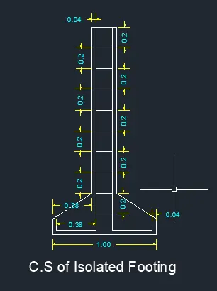
2:Isolated footing
A) Aim:-
To draw a figure C2 of Isolated footing.
B)Introduction:-
The isolated footing is used to support individual columns. They can be either of steeped type or have projections in the concrete-base. In the case of heavily loaded columns, steel reinforcement is provided in both the directions in a concrete bed. To draw this figure (Isolated footing) used command are:- Line, Polyline, Copy, Mirror and Dimlinear.
C)Procedure:-
Step-1:-
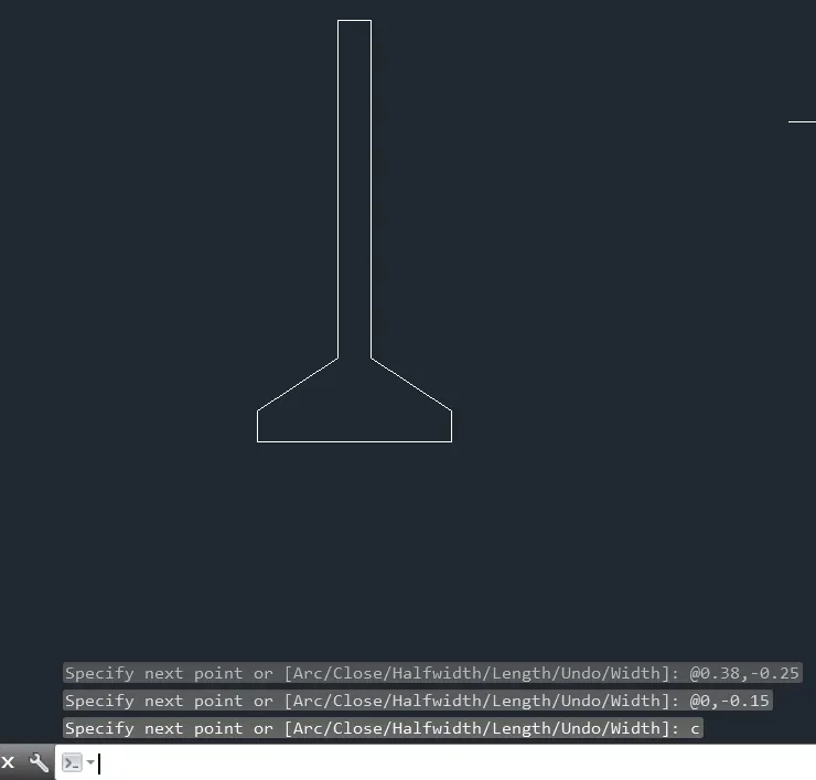
- Type the command "Pl" to draw the polylines.
- Specify start point: 3,3
- Specify next point: @0,0.15
- Specify next point: @0.38,0.25
- Specify next point: @0,1.60
- Specify next point: @0.24,0
- Specify next point: @0,-1.60
- Specify next point: @0.38,-0.25
- Specify next point: @0,-0.15
- Type "C" for close.
Step-2:-
- Type the command "Pl" to draw the polylines.
- Specify start point: 3.04,3.08
- Specify next point: @0,-0.04
- Specify next point: @0.38,0
- Specify next point: @0,1.96
- Type "E" for exit.
Step-3:-
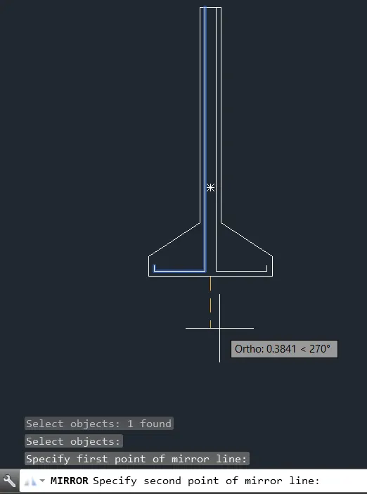
- Type the command "Mi" to mirror the object.
- Specify objects: Select the Polyline (i.e. draw in the step-2)
- Specify first point of mirror line: select the footing mid point at base
- Erase source objects?: No
Step-4:-
- Type the command "L" to draw the lines.
- Specify first point: 3.42,4.80
- Specify next point: 3.58,4.80
- Press "Esc" for close the command.
Step-5:-
- Type the command "Co" copy the lines.
- Select the object: Select the line (i.e. draw in the step-4)
- Specify base point
- Specify second point: Choose Array
- Enter number of items to array: 9
- Specify second point: 0.2
- Press "Exit" for close the command.
Step-5:-
- Type the command "Dimlin" to measure the dimensions of the objects.
- Specify first extension line origin.
- Specify second extension line origin.
Result:-
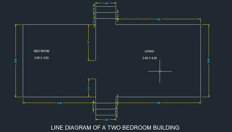
3:Line diagram of a two bedroom building
A) Aim:-
To draw a figure C3 of two bed room building.
B)Introduction:-
The desired line diagram is created in AutoCAD by using the commands:- polyline, line, offset, dimlin.
C)Procedure:-
Step-1:-
- Type the command "Pl" to draw the polylines.
- Specify start point: 3,3
- Specify next point: @0,3.60
- Specify next point: @3.60,0
- Specify next point: @0,0.90
- Specify next point: @1,0
- Specify next point: @0,-0.90
- Specify next point: @4.20,0
- Specify next point: @0,-0.36
- Specify next point: @-4.20,0
- Specify next point: @0,-0.90
- Specify next point: @-1,0
- Specify next point: @0,0.90
- Type "C" for close.
Step-2:-
- Type the command "L" to draw the lines.
- Specify first point: 6.60,3.00
- Specify next point: 0.90 in +ve y-axis direction
- Press "Esc" for close the command.
Step-3:-
- Type the command "L" to draw the lines.
- Specify first point: 6.60,6.60
- Specify next point: 1.80 in -ve y-axis direction
- Press "Esc" for close the command.
Step-4:-
- Type the command "L" to draw the lines.
- Specify first point: 6.60,2.70
- Specify next point: 1.0 in +ve x-axis direction
- Press "Esc" for close the command.
Step-5:-
- Type the command "L" to draw the lines.
- Specify first point: 6.60,2.40
- Specify next point: 1.0 in +ve x-axis direction
- Press "Esc" for close the command.
Step-6:-
- Type the command "L" to draw the lines.
- Specify first point: 6.60,6.90
- Specify next point: 1.0 in +ve x-axis direction
- Press "Esc" for close the command.
Step-7:-
- Type the command "L" to draw the lines.
- Specify first point: 6.60,7.20
- Specify next point: 1.0 in +ve x-axis direction
- Press "Esc" for close the command.
Step-8:-
- Type the command "Dimlin" to measure the dimensions of the objects.
- Specify first extension line origin.
- Specify second extension line origin.
Result:-
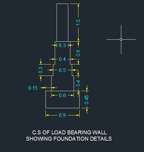
4:Load bearing wall showing foundation details
A) Aim:-
To draw a figure C4 of Load bearing wall showing foundation details.
B)Introduction:-
A load-bearing wall or bearing wall is a wall that is an active structural element of a building, that is, it bears the weight of the elements above wall, resting upon it by conducting its weight to a foundation structure. To draw the load bearing wall is created in AutoCAD by using the commands:- rec, polyline, dimlin.
C)Procedure:-
Step-1:-
- Type the command "Rec" to draw the rectangles.
- Specify first corner point: 3,3
- Specify other corner point: enter "d" [Or select Dimension]
- Specify length for rectangle: 0.9
- Specify width for rectangle: 0.45
- Specify other corner point: click cursor in Y-direction.
Step-2:-
- Type the command "Pl" to draw the polylines.
- Specify start point: 3.15,3.45
- Specify next point: @0,0.40
- Specify next point: @0.05,0
- Specify next point: @0,0.30
- Specify next point: @0.05,0
- Specify next point: @0,0.30
- Specify next point: @0.05,0
- Specify next point: @0,0.60
- Specify next point: @0.40,0
- Specify next point: @0,-0.60
- Specify next point: @0.05,0
- Specify next point: @0,-0.30
- Specify next point: @0.05,0
- Specify next point: @0,-0.40
- Press "Esc" for close the command.
Step-3:-
- Type the command "Rec" to draw the rectangles.
- Specify first corner point: 3.3,4.75
- Specify other corner point: enter "d" [Or select Dimension]
- Specify length for rectangle: 0.3
- Specify width for rectangle: 1.0
- Specify other corner point: click cursor in Y-direction.
Step-4:-
- Type the command "Dimlin" to measure the dimensions of the objects.
- Specify first extension line origin.
- Specify second extension line origin.
Result:-
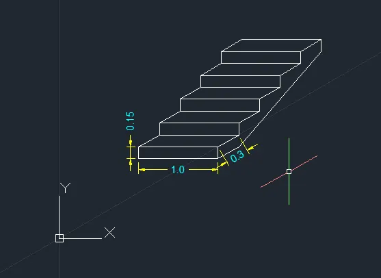
5:Isometric view of steps
A) Aim:-
To draw a isometric view of steps (dwg no C5).
B)Introduction:-
The desired isometric view of steps is created in AutoCAD by using the commands:- rec, line, copy, dimlin.
C)Procedure:-
Step-1:-
- Turn on "Isometric drafting" mode in "Isoplane right".
- Type the command "Rec" to draw the rectangles.
- Specify first corner point: 1,1
- Specify other corner point: enter "d" [Or select Dimension]
- Specify length for rectangle: 1.0
- Specify width for rectangle: 0.15
- Specify other corner point: click cursor in Y-direction.
Step-2:-
- Type the command "L" to draw the Lines.
- Specify start point: select the top left corner of the rectangle
- Specify next point: 0.3 in +ve z-direction
- Specify next point: @1.0,0
- Specify next point: @0,-0.15
- Press "Esc" for close the command.
Step-3:-
- Type the command "Co" copy the lines.
- Select the object: Select the line (i.e. draw in the step-2)
- Specify base point
- Specify second point: Choose both point of rectangle i.e top right corner and bottom right corner.
- Press "Exit" for close the command.
Step-4:-
- Type the command "Co" copy the lines.
- Select the object: Select the objects i.e. draw in the step- 1,2&3 , except the line copied at right corner of the bottom of the rectangle.
- Specify base point
- Specify second point: Copy the objects at a distance of 0.3,0.15 in (Z,Y)-directions respectively.
- Draw 5 steps.
- Press "Exit" for close the command.
Step-5:-
- Type the command "L" to draw the Lines.
- Specify start point: select the top right corner of the top step
- Specify next point: 0.15 in -ve y-direction
- Press "Esc" for close the command.
Step-6:-
- Type the command "L" to draw the Lines.
- Specify start point: select the end point (i.e drawn in step-5)
- Specify next point: select the end point (i.e copied(2nd one) in step-5)
- Press "Esc" for close the command.
Step-4:-
- Type the command "Dimlin" to measure the dimensions of the objects.
- Specify first extension line origin.
- Specify second extension line origin.
Result:-
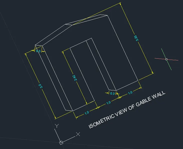
6:Isometric view of Gable wall
A) Aim:-
To draw a isometric view of gable wall (dwg no C6).
B)Introduction:-
Gable wall is the vertical triangular wall between the sloping ends of gable roof. The desired isometric view of gable wall is created in AutoCAD by using the commands:- polyline, line, copy, dimlin.
C)Procedure:-
Step-1:-
- Type the command "Pl" to draw the polylines.
- Specify start point: 1,1
- Specify next point: @0,3.0
- Specify next point: @1.5,0.25
- Specify next point: @0,-3.0
- Specify next point: @-1,0
- Specify next point: @0,2.42
- Specify next point: @-1,0
- Specify next point: @0,-2.42
- Type "C" for close.
Step-2:-
- Type the command "L" to draw the Lines.
- Specify start point: select the bottom left corner.
- Specify next point: 0.3 in +ve z-direction
- Press "Esc" for close the command.
Step-4:-
- Type the command "Co" copy the lines.
- Select the object: Select the line (i.e. draw in the step-2)
- Specify base point
- Specify second point: Choose portion at ehich the line to be copied (As shown below).
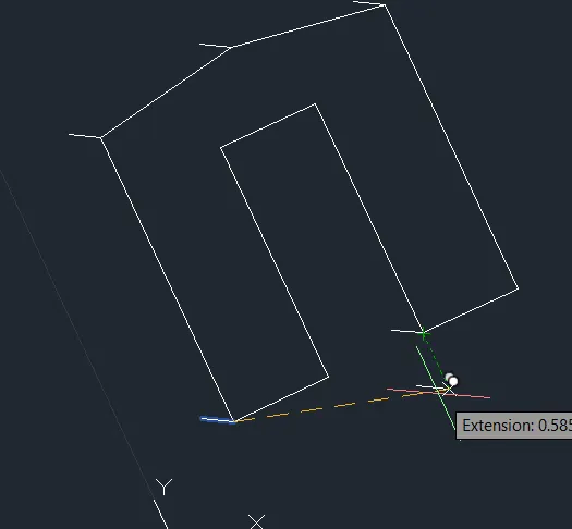
- Press "Exit" for close the command.
Step-5:-
- Type the command "L" to draw the Lines.
- Specify start point: select the left corner of the line(i.e drawn in step-2).
- Specify next point: join next 3 copied lines(i.e. drawn in step-4)
- Specify next point: end point of remains last line to the opposite line with perpendicular to the y-direction.
- Press "Esc" for close the command.
Step-6:-
- Type the command "Dimlin" to measure the dimensions of the objects.
- Specify first extension line origin.
- Specify second extension line origin.
Result:-