Drafting of various geometries using Chamfer, Fillet tool in AutoCad
C1
AIM: To draw the given drawing using AutoCAD software
PROCEDURE:
- In command prompt, type UNITS and set to decimal, precision = 0.00.
STEP 1: For line diagram
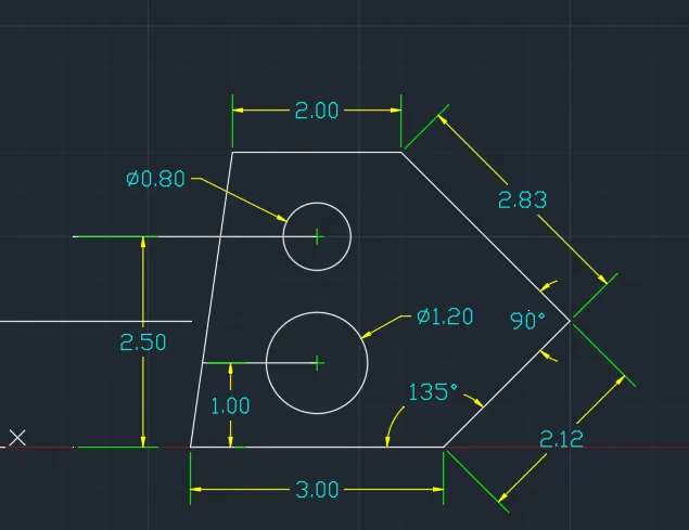
- In command prompt, type LINE and specify first point as (1,1) and assign values as @3<0, @2.12<45, @2.83<135, @2<180 and click close.
STEP 2: For circle
- In command prompt, type OS (object snap) and click on midpoint, endpoint and centre
- In command prompt, type line, take first point at midpoint of line 3 and assign @1<90
- In command prompt, type Circle and centre as previous line end point and assign diameter 1.20
- In command prompt, type line, take first point at midpoint of line 3 and assign @2.50<90
- In command prompt, type Circle and centre as previous line end point and assign diameter 0.80
- In command prompt, type TRIM and remove the unwanted lines.
RESULT:
C2
AIM: To draw the given drawing using AutoCAD software
PROCEDURE:
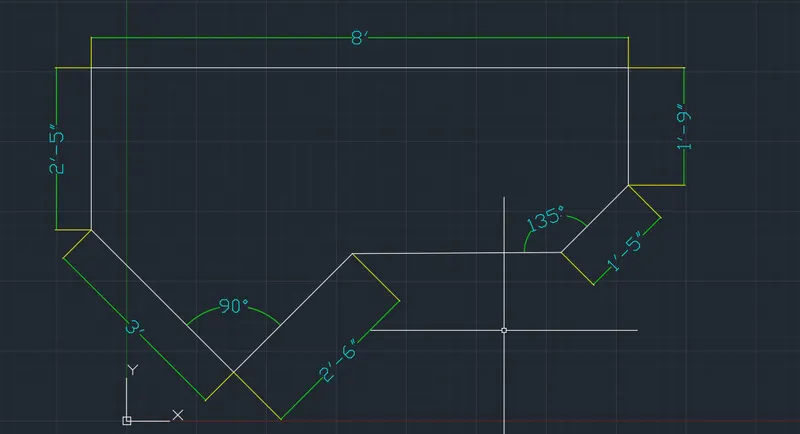
- In command prompt, type UNITS and set to Architectural, precision = 0'-0"
- Select polar tracking 45,90,135,180
- In command prompt, type LINE and with the help of cursor assign values as
- move the cursor to the left at 45 degree and assign value as 3'
- move the cursor to the Top at 90 degree and assign value as 2'-5"
- move the cursor to the Right at 0 degree and assign value as 8'
- move the cursor to the Bottom at 270 degree and assign value as 1'-9"
- In command prompt, type LINE and with the help of cursor assign values as 2'-6" at 45 degree to right and move the cursor to the right at 0 degree and assign value as 3'-1" and finally assign value of 1'-5" at 45 degree to the previous point with the cursor.
RESULT:
C3
AIM: To draw the given drawing using AutoCAD software
PROCEDURE:
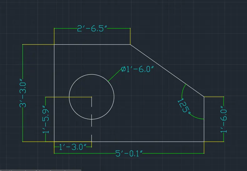
- In command prompt, type UNITS and set to Engineering, precision = 0'-0.0"
STEP 1: For line diagram
- select polar tracking 45,90,135,180
- In command prompt, type LINE and specify first point as (1,1) and assign values with the help of cursor by polar tracking
- Move the cursor in 90 angle and assign value as 3'-3.0", move the cursor in 0 angle form previous line end point assign value as 2'-6.5"
- In command prompt, type LINE and specify first point as (1,1) and assign values with the help of cursor by polar tracking by Moving the cursor in 0 angle from the previous line endpoint assign value as 5'-0.1", then move the cursor in 90 angle from previous line endpoint and assign value as 1'-6.0"
- move the cursor in 125 angle and join the previous line endpoint to the 2'-6.5" line and click close.
Step 2: For circle
- In command prompt, type CIRCLE and specify point at (1'-3.0", 1'-5.9") and assign diameter as 1'-6.0"
RESULT:
C4
AIM: To draw the given drawing using AutoCAD software
PROCEDURE:
- In command prompt, type UNITS and set to decimal, precision = 0.00.
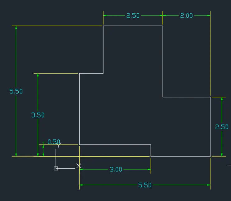
- In command prompt, type LINE and specify first point as (1,1) and assign values as @3<90, @1<0, @2<90, @2.50<0, @3<270, @2<0, @2.5<270, @2.5<180, @0.5<90, @3<180.
RESULT:
C5
AIM: To draw the given drawing using AutoCAD software
PROCEDURE:
- In command prompt, type UNITS and set to decimal, precision = 0.00.
STEP 1: For line diagram
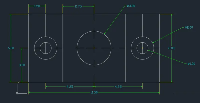
- In command prompt, type LINE and specify first point as (1,1) and assign values as @11.5<0, @6<90, @11.5<180, @6<270
- In command prompt, type LINE and specify point at (4,1) and assign values as @6<90
- In command prompt, type LINE and specify point at (9.5,1) and assign values as @6<90
STEP 2: For Circles
CENTER CIRCLE: In command prompt, type Circle and specify point at (6.75,4) as centre and assign diameter as 3
LEFT SIDE CIRCLE :
- In command prompt, type Circle and specify point at (2.5,4) as centre and assign diameter as 1
- In command prompt, type Circle and specify point at (2.5,4) as centre and assign diameter as 2
RIGHT SIDE CIRCLE:
- In command prompt, type Circle and specify point at (11,4) as centre and assign diameter as 1
- In command prompt, type Circle and specify point at (11,4) as centre and assign diameter as 2
RESULT:
C6
AIM: To draw the given drawing using AutoCAD software
PROCEDURE:
- In command prompt, type UNITS and set to decimal, precision = 0.00.
Step 1: For rectangle at LEFT SIDE
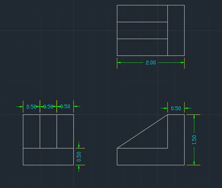
- In command prompt, type LINE and specify point at (1,1) and assign values as @1.5<0, @0.5<90, @1.5<180, @1<90, @1.5<0, @1<270
- In command prompt, type LINE and specify point at (1,1) and assign value @0.5<90
- In command prompt, type OFFSET and give distance as 0.5 from left end line and make 2 horizontal offsets at 0.5 distance between them.
STEP 2: For Rectangle at TOP
- In command prompt, type LINE and specify point type @2<0, @1.5<90, @2<180, @1.5<270
- In command prompt, type OFFSET and distance as 0.5 and assign vertical line of 0.5 from right side and similarly two offset line of 0.5 distance in horizontal are done.
STEP 3: For Center drawing
- In command prompt, type XLINE and type horizontal and select left side rectangle horizontal lines
- In command prompt, type XLINE and type vertical and select Top side rectangle vertical lines
- In command prompt, type TRIM and trim the unwanted lines
- In command prompt, type LINE and join the line of top edge and inverted L top edge.
RESULT:
C7
AIM: To draw the given drawing using AutoCAD software
PROCEDURE:
- In command prompt, type UNITS, set to decimal and units to scale as Millimetres, precision = 0.00.
STEP 1:
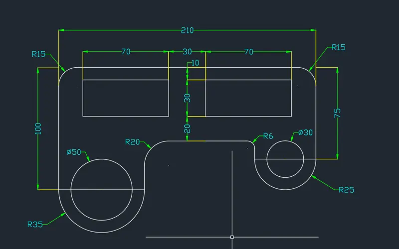
- In command prompt, type LINE and specify point at anywhere and assign value as @100<90, @210<0, @75<270
- In command prompt, type FILLET and select radius as 15 and select the 100 line and 210 line edge to get radius.
- In command prompt, type FILLET and select radius as 15 and select the 210 line and 75 line edge to get radius.
STEP 2:
- In command prompt, type LINE and specify point at 100 line bottom end and assign @70<0
- In command prompt, type OBJECT SNAP and click on midpoint and endpoint
- In command prompt, type CIRCLE and select center at mid point of 70 line assign radius 35
- In command prompt, type CIRCLE and select center at mid point of 70 line assign diameter 50
STEP 3:
- In command prompt, type LINE and specify point at 75 line bottom end and assign @50<180
- In command prompt, type CIRCLE and select center at mid point of 50 line assign radius 25
- In command prompt, type CIRCLE and select center at mid point of 50 line assign diameter 30
STEP 4:
- In command prompt, type TRIM and trim R35 circle top
- In command prompt, type LINE selct point at right end of the 70 line and assign value as @40<90
- In command prompt, type TRIM and trim R25 circle top
- In command prompt, type LINE selct point at right end of the 50 line and assign value as @30<90
- In command prompt, type LINE and select the new end points and make a line
- In command prompt, type FILLET and radius as 20 and select verticle line of 70 line and horizantal line at midpoint
- In command prompt, type FILLET and radius as 6 and select verticle line of 50 line and horizantel line at midpoint
STEP 5:
- In command prompt, type REC and select refrence point at mid point of 210 line at top 15 left and 10 down dimension as length, widhth as 70,70
- In command prompt, type COPY and select the geometric center of rectangle and paste at 30 towards right.
RESULT:
C8
AIM: To draw the given drawing using AutoCAD software
PROCEDURE:
- In command prompt, type UNITS and set to decimal, precision = 0.00.
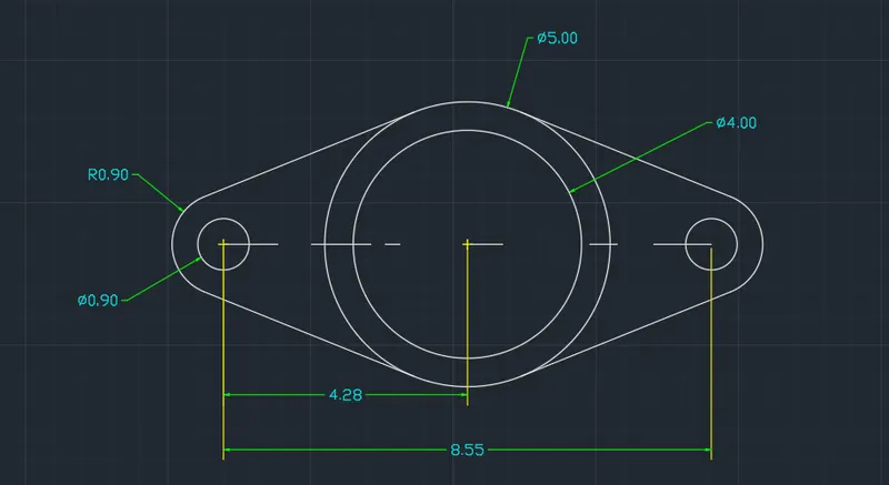
- In command prompt, type LINE and specify point at anywhere and assign value as 8.55
- In command prompt, type OBJECT SNAP and click on endpoint and midpoint
STEP 1: For MIDDLE CIRCLE
- In command prompt, type CIRCLE and select centre from mid-point of the line and assign diameter as 4
- In command prompt, type CIRCLE and select centre from mid-point of the line and assign diameter as 5
STEP 2: For Left side circles
- In command prompt, type CIRCLE and select centre at the Left endpoint of the line and assign diameter 0.90
- In command prompt, type CIRCLE and select centre at the Left endpoint of the line and assign Radius 0.90
STEP 3: For Right side circles
- In command prompt, type CIRCLE and select centre at the Right endpoint of the line and assign diameter 0.90
- In command prompt, type CIRCLE and select centre at the Right endpoint of the line and assign Radius 0.90
STEP 4: Join the left and right circles to the middle circle respectively by the tangents
- In command prompt, type TRIM and trim of the unwanted lines.
RESULT:
C9
AIM: To draw the given drawing using AutoCAD software
PROCEDURE:
- In command prompt, type UNITS and set to Architectural, precision = 0'-0"
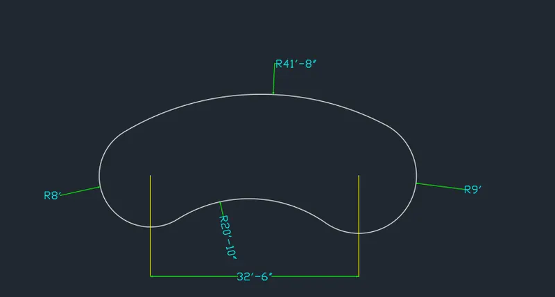
- In command prompt, type LINE and specify start point anywhere and assign value as 32'-6"
STEP 1: For Left and right circles
- In command prompt, type CIRCLE and select the centre at the Left end point of the line and assign radius as 8'
- In command prompt, type CIRCLE and select the centre at the Right end point of the line and assign radius as 9'
STEP 2: For top arc
- In command prompt, type CIRCLE and select centre from left end point of line, assign value as (41'-8" (-) 8') = 33'-8".
- In command prompt, type CIRCLE and select centre from Right end point, assign value as (41'-8" (-) 9') = 32'-8".
- In command prompt, type OBJECT SNAP and click on Intersection
- In command prompt, type CIRCLE and select centre from intersection of new two circles at bottom and assign value as 32'-6"
- In command prompt, type TRIM and trim the extra line other than required lines and arc
STEP 3: For Bottom Arc
- From ribbon select circle of tan, tan, radius and select the 1st tangent at 8' circle and 2nd tangent at 9' circle and assign radius as 20'-10".
RESULT:
C10
AIM: To draw the given drawing using AutoCAD software
PROCEDURE:
- In command prompt, type UNITS and set to decimal, precision = 0.00.
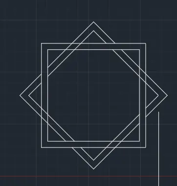
- In command prompt, type REC, type dimensions and assign values of length, width as 5,5 and offset the rectangle and copy the same rectangle and rotate to diamond shape
- In command prompt, type TRIM and trim the unwanted lines to get desired diagram.
RESULT:
C11
AIM: To draw the given drawing using AutoCAD software
PROCEDURE:
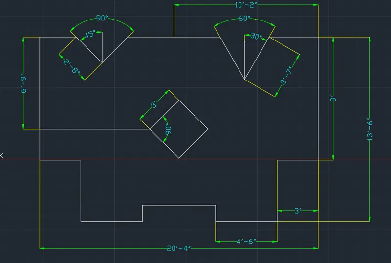
- In command prompt, type UNITS and set to Architectural, precision = 0'-0"
STEP 1: For line diagram
- Select polar tracking as 45,90,135,180
- In command prompt, type PLINE and specify point anywhere and assign values by the help of cursor
- Move cursor at 270 angle and assign value as 9'
- move cursor at 0 angle and assign value 3'
- move cursor at 90 angle and assign value 4'-6"
- move cursor at 0 angle and assign value 4'-6"
- move cursor at 90 angle and assign value 1'-2"
- move cursor at 0 angle and assign value 4'-6"
- move cursor at 270 angle and assign value 1'-2"
- move cursor at 0 angle and assign value 4'-6"
- move cursor at 90 angle and assign value 4'-6"
- move cursor at 0 angle and assign value 3'
- Move cursor at 90 angle and assign value as 9'
- Move cursor at 180 angle and assign value as 3'-7"
- Move cursor at 240 angle and assign value as 3'-7"
- Move cursor at 120 angle and assign value as 3'-7"
- Move cursor at 180 angle and assign value as 6'-3"
- Move cursor at 225 angle and assign value as 2'-8"
- Move cursor at 135 angle and assign value as 2'-8"
- Move cursor at 180 angle and assign value as 2'-8" and click close
STEP 2: For Rectangle
- In command prompt, type OBJECT SNAP and click on midpoint and endpoint
- In command prompt, type LINE and specify point at top mid-point and assign value 6'-9"
- In command prompt, type REC and select dimension assign length, width as 3,3
- In command prompt, type OBJECT SNAP and click on Geometric centre
- In command prompt, type ROTATE and select rectangle and rotate at geometric centre of rectangle to diamond shape
RESULT: