Electric doorbell and Thermistor-based automatic fan using SIMULINK
Aim:
- Modeling a solenoid operated doorbell
- Modeling a thermistor operated automatic fan
Objectives:
- Simulating a situation where the circuit switch is closed for 2 seconds and then released to observe the physical movement of the solenoid plunger hitting the doorbell
- Simulating a situation where a thermistor is used to sense the temperature of a heater to turn on/off a fan
Background for A:
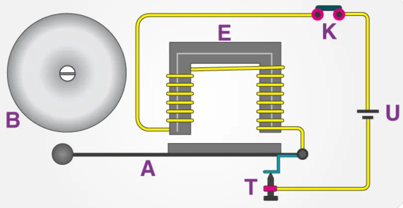
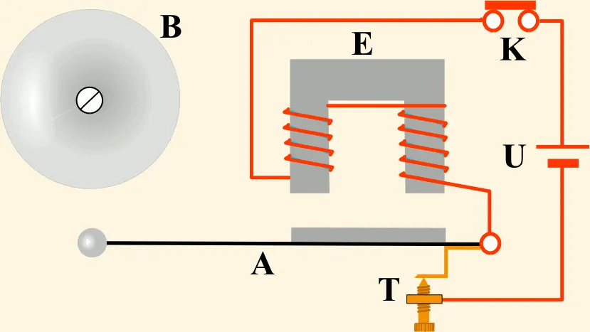
The figures above represent a simple circuit, that triggers a sound referred to as the "doorbell" at the completion of the circuit. The circuit will be modelled with a constant voltage source (the battery 'U') so the only component that completes/incompletes the circuit is the switch, which is represented by 'K'.
Once the current flows through the circuit and gets to the Solenoid (the coil of wires wrapped around 'E'), an electromagnetic field is created. Marked by 'A' can be considered an armature made of iron/nickel, which has magnetic properties and turns into a temporary magnet, in turn getting attracted to the solenoid which is basically an electromagnet. This attraction results in the armature striking the bell 'B' and making the sound.
Since iron/nickel are soft magnetic materials with temporary magnetism characteristics, as soon as the switch is open, the current stops flowing and the armature returns to its original position via a spring.
This entire situation is modelled below:
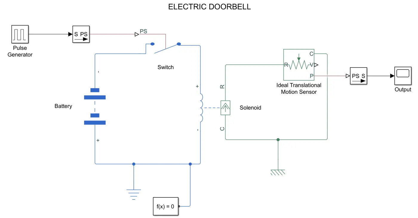
- A pulse is generated, which gives instructions to the switch that it must be closed for 2 seconds and then open.
- Once the switch is closed, as explained previously, the current starts flowing in the circuit and the solenoid starts acting like an electromagnet.
- To see the effect of the solenoid on the armature that experiences motion to strike the bell, a translational motion sensor was added to detect the output.
Output:
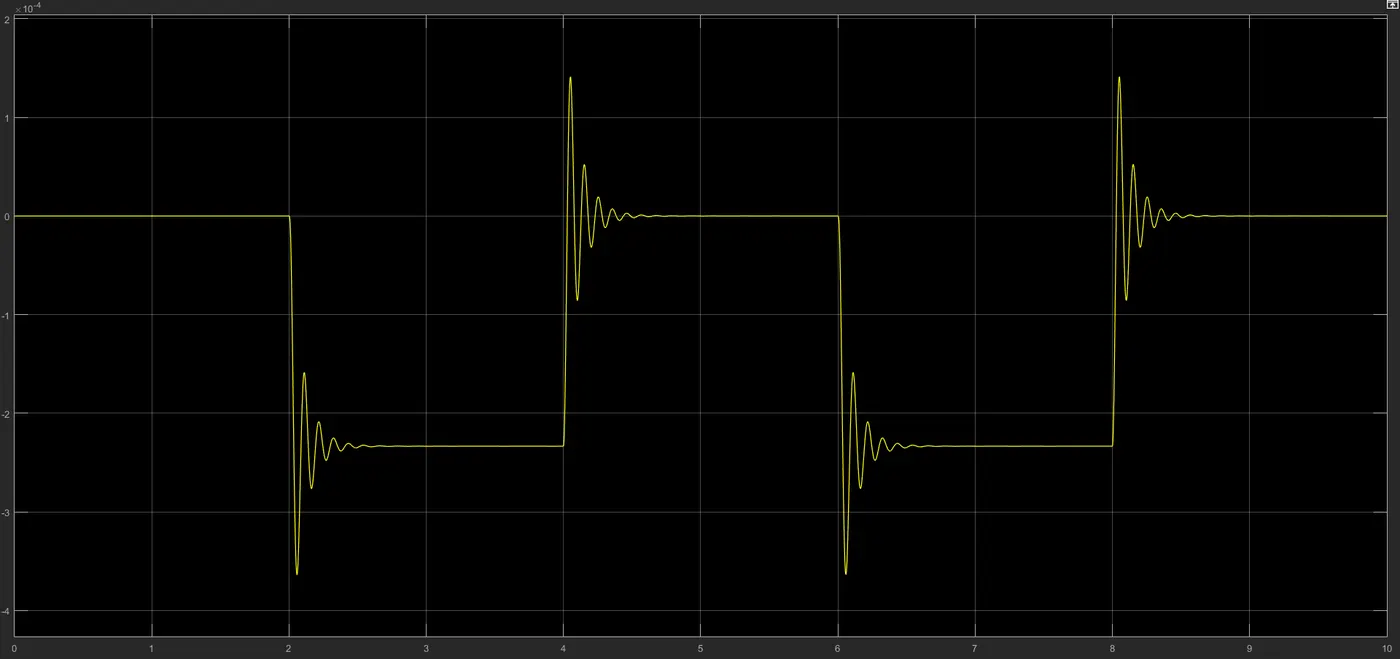
- With a phase delay set for 2 seconds, the pulse only starts sending the signal to close the switch at 2 seconds.
- At 2 seconds a sudden spike in motion in sensed, which is the first time the armature strikes the bell.
- There is evident vibration from the striking, which damps out within half a second of the switch being closed, giving the final position of the armature while the current in the circuit is still flowing until 4 seconds (net time of 2 seconds as per the requirement). Changing parameters such as spring costant and damping coefficient will result in smoother motion.
- At 4 seconds, the switch is open again, which means the armature moves back to its original position via the spring decompression, which is in the opposite direction.
- Two full cycles are shown
With spring constant halved and damping quadrupled:
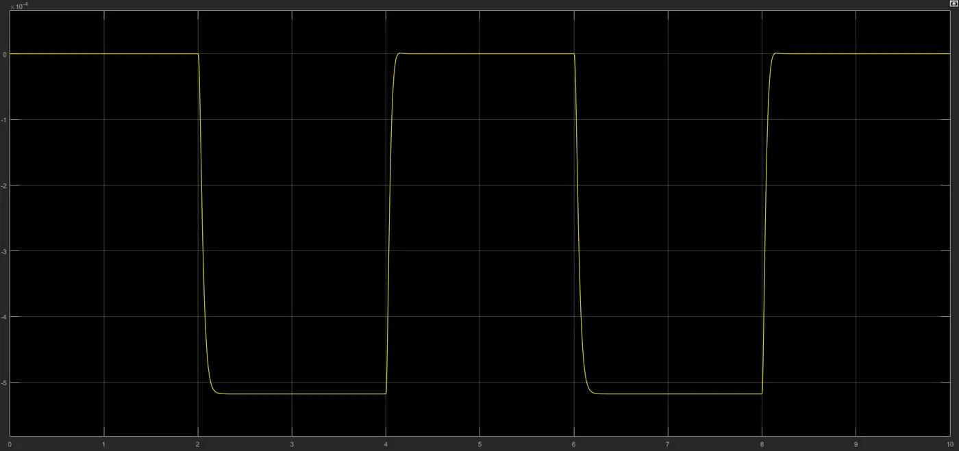
- More tightly-sprung spring and higher damping coefficient results in a smoother curve
- Plunger/Armature mass is another parameter that could be changed. The greater the mass of whatever is striking the bell, the more the vibrations experienced by the motion sensor
Background for B:

The gif above demonstrates how a thermistor senses the temperature of a heat source and accordingly decides whether to send the signal to turn the fan on or not.
A thermistor is a thermal resistor whose resistance is dependent on the temperature it experiences. The thermistor that is to be modelled is a NTC (negative temperature coefficient) thermistor, whose resistance decreases with increase in temperature, following an inversely proportional relationship between the two parameters.
This thermistor-based automatic fan is an experiment where the fan is turned on only if the temperature experienced by the thermistor is above a certain value, since that will lead to lower resistance of the thermistor. As the resistance of the thermistor decreases, it will use up lesser voltage provided from the battery, allowing for enough voltage to be used by other components too. This leftover voltage is what can be used to power the fan.
This entire situation is modelled below:
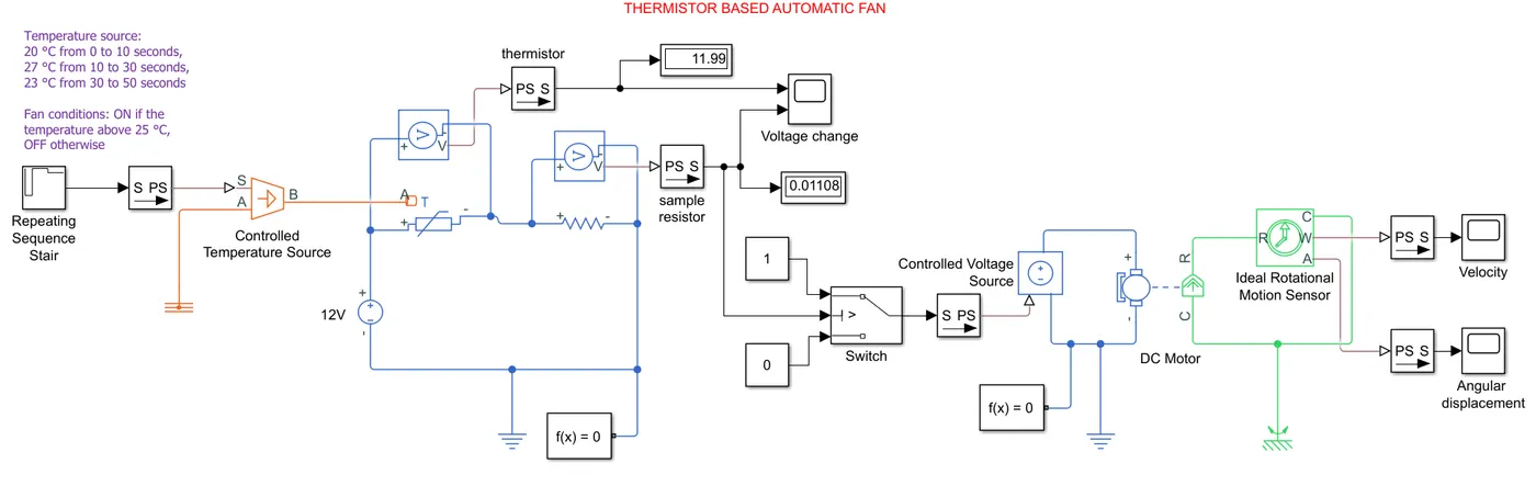
- A repeating sequence stair was used as a signal builder for the multiple temperatures, which was then fed to the controlled temperature source, since a heater component does not exist in Simulink/Simscape.
- The thermistor received those temperatures as inputs and its resistance varied accordingly, which led to it using a different amount of voltage everytime the temperature was different.
- A sample resistor with fixed resistance (1`Omega`) is incorporated so that the total voltage (12V) in the circuit can be shared across two components, continuously changing according to the changing resistance of the thermistor. This is demonstrated graphically below under Output #1.
- The voltage used by the sample resistor is set as a threshold i.e. 0.01199V is the voltage used by the sample resistor when the temperature of the thermistor is 25 degrees C. Beyond this temperature is when the automatic fan should be turned on as per the requirement. Hence, whenever the voltage sensor of the sample resistor senses greater than 0.01199V, that is when it should be allowed to pass through to the switch.
- A switch is used to meet this if-condition threshold of the voltage, which then allows the voltage to pass through to a DC motor.
- The DC motor then powers the fan, and a rotational motion sensor is used to detect the outputs.
Output #1: Change in voltage used by thermistor and sample resistor
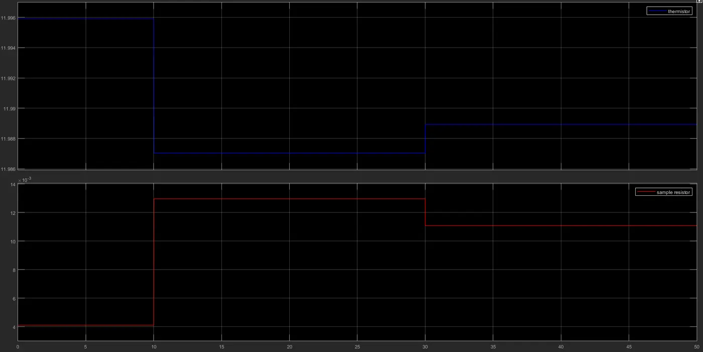
- The temperature is only 20 degrees C from 0 to 10 seconds, which is why the the thermistor takes up almost the entire 12V, leaving very little for the sample resistor.
- From 10 to 30 seconds is when the temperature increases to 27 degrees, hence we see the shift in voltage usage in both components as the resistance of the thermistor decreases.
Output #2: Angular velocity of fan
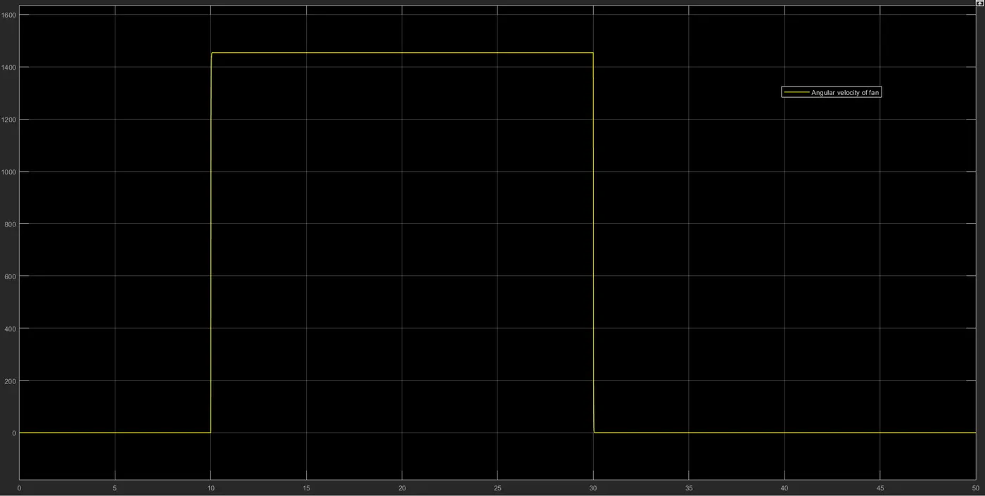
- From 0 to 10 seconds and 30 to 50 seconds, the temperature experienced by the thermistor is below 25 degrees C, which is why the fan isn't turned on.
- From 10 to 30 seconds, however, the temperature is 27 degrees C, and hence the fan is turned on and experiences angular velocity of about 1450 rad/s.
Output #3: Angular displacement of fan
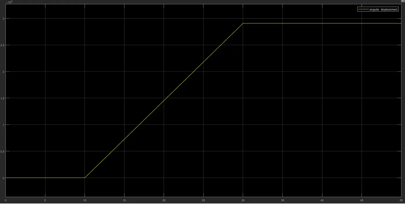
- The fan experiences 29,000 rad of angular displacement in 20 seconds when the fan is turned on from 10 to 30 seconds
- To put things more clearly, 1450 rad/s is about 231 revolutions per second, so in 20 seconds this fan is able to make 4615 revolutions (equivalent to 29,000 radians).