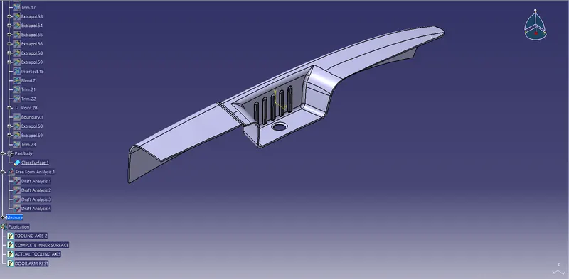
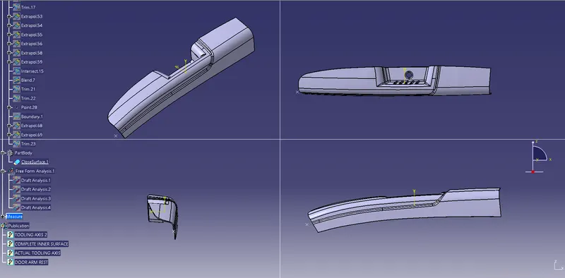
Door Arm Rest Week 8 Challenge
Objective: Creation of class B and C surface for the given class A model and creating solid model of the given class A surface
Steps:
1. Creation of tooling axis
- Extract the base surface. Create a point on it. insert the axis system at the point created, Get intersection curve in xz plane and the model. Draw two lines on intersection curve as shown below. Bisect the two lines to get the tooling axis.
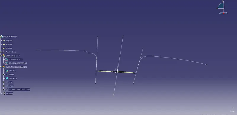
2. Draft analysis
- Go to insert - Analysis - feature draft analysis. Before that customize view parameter mode to material. click on the compass icon and align it with the tooling axis and click on the surface, we will get our results
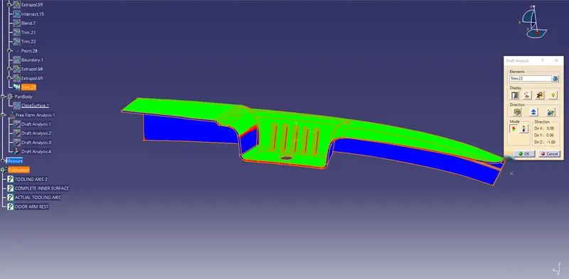
From the above image it is seen that surface in green colour has greater than 3 deg draft which is most required for tooling feasibility. However on surface is in blue color means it has negative draft angle. To ease the part ejection we need to provide a side core. The axis of side core is created as explained below.
3. Creation of second tooling axis
- Extract the surface. Create a point on it. insert the axis system at the point created, Get intersection curve in yz plane and the model. Draw two lines on intersection curve as shown below. Bisect the two lines to get the tooling axis.
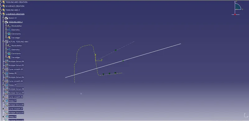
4. Draft analysis for 2nd tooling axis
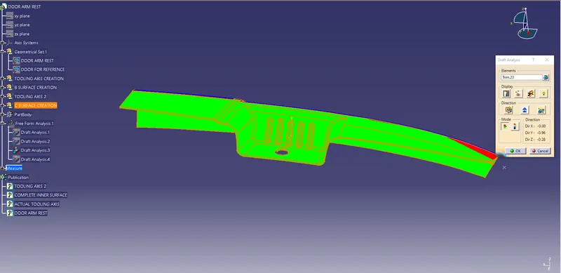
From the above image it is seen that surface in green colour has greater than 3 deg draft which is most required for tooling feasibility. So for the given class A surface we need two tooling directions, one for main core and cavity and another for side core.
5. B-Surface creation
- Extract the top surfaces, untrim them, extrapolate them. offset them to a value equal to thickness of the model. Trim unwanted edges.
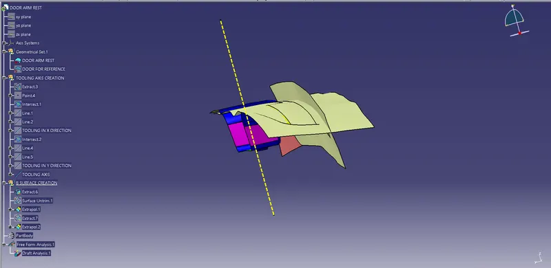
- After Applying fillet values
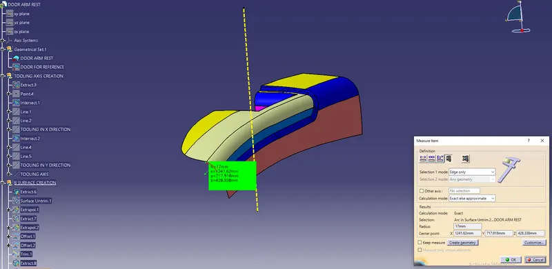
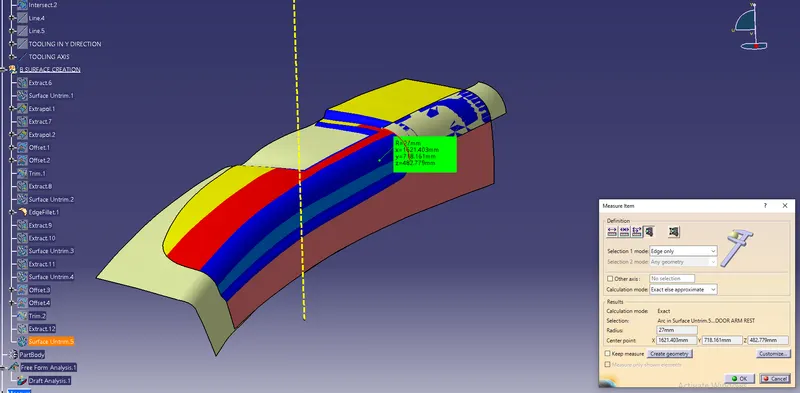
- Formation of side filleted edge: Insert axis system at the intersection point as shown. click on intersect with 3D element. get the inetrsection line. Draw a line with tangency constraint to this intersection curve. By multiple extract command get the guide curve. Perofrm curve smoothening. use sweep command to get the surface
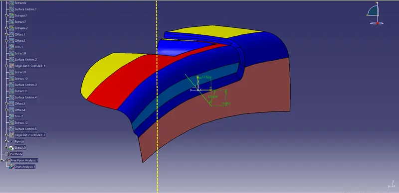
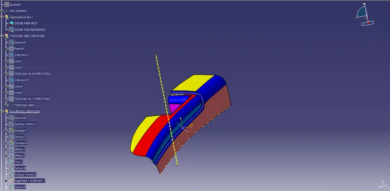
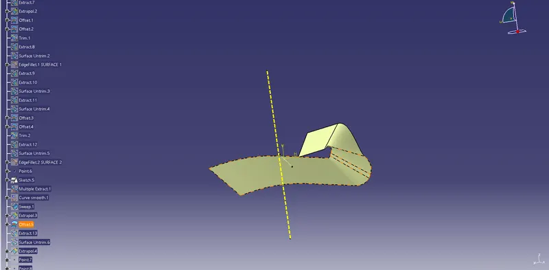
- Similarly extract the remaining surfaces. After trimming and filleting the image is shown below
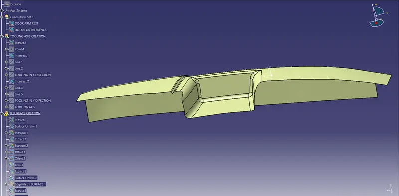
6. Creation of C surface
- C surface was created using the following commands
- Sweep with draft direction
- Sweep with reference to surface
- Multisection surface command
7. Use C surface to join the class A and class B surface.
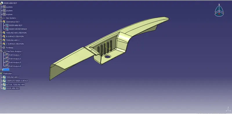
8. Making solid body
- Use close surface command in part design work bench to make the solid body