Door Arm Rest Week 8 Challenge
AIM
To develop Class A surface input provided into a product design following the OEM design standards using CATIA V5 Surface
workbench and to ensure that the product is manufacturable by injection molding.
OBJECTIVE
The project report deals with the steps and procedures followed while creating a Door arm rest console design using CATIA V5 surface workbench.
It explains the methods I followed for creating the main tooling axis, side core axis, Class B surface, Class C surface and
final closed body creations.
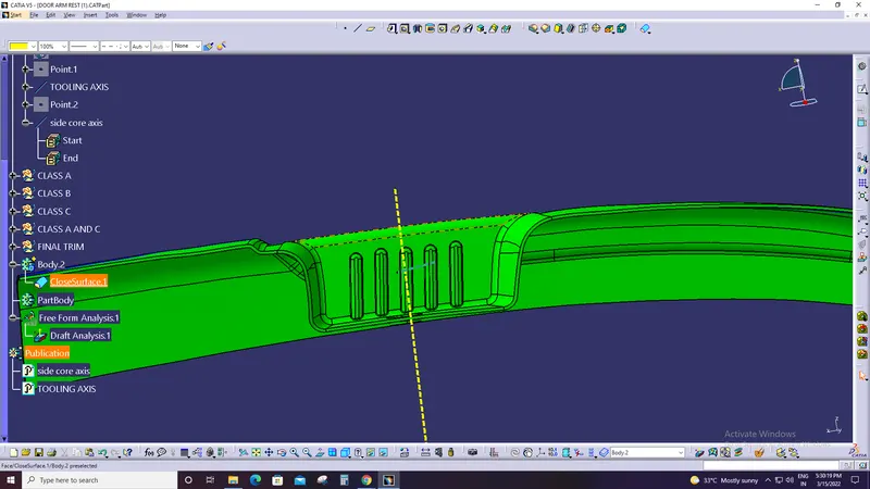
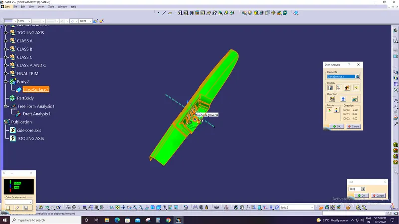
It also explains the draft analysis performed to check the manufacturability of the product using injection molding.
The report deals with the Design Life Cycle followed in Automotive industry. The common stages of Design Life cycle in Automotive
industry are;
1) Concept sketches
2) Class A Surface creation
3) NPD CAD
4) Clay modelling
(The common stages of Design Life cycle in Automotive industry)
Class A Surface
In Automotive industry there will be a dedicated team who will perform the aesthetic designing of various components including the
whole vehicle. They will create various concept sketches after ideation.
After that, they will also create a Class A surface of the product. This class A surface is then passed over to the NPD CAD team. They will initially inspect the Class A surface in order to check if
the design is manufacturable or if it is following the engineering principles.
If there are any issues about the design, they will contact the product design team and will ask to modify the Class A surface in order to solve the problem. Here I received the Class A surface
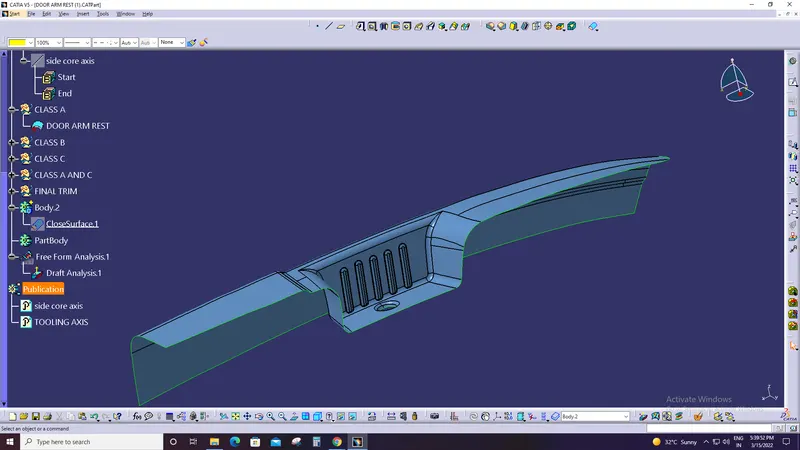
of the Door Arm rest console as shown below.
The blue colour portion is the Arm rest console. I separated it as shown in the below image and inserted in a new geometrical set
named 'Class A' and published.
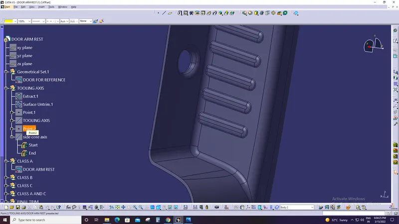
TOOLING AXIS
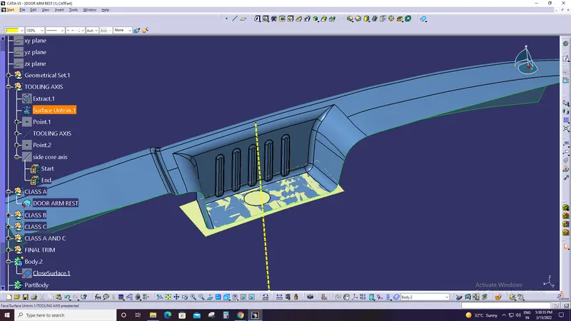
performed the draft analysis after creating a tooling axis using the opposite faces of the pocket.
The green colour represents the walls above 3 degree. The blue colour is walls from 0-3 degree. The red colour represents the
negative degree. Here the green colour which is above 3 degree is manufacturable using injection molding. As the red region is not
possible to eject along the main tooling axis,
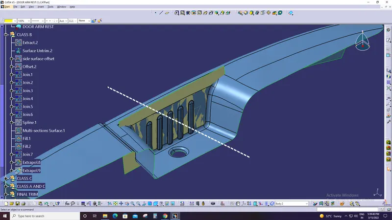
the Class A surface should be modified by the styling team. add a side core which will increase the manufacturing cost.
But in this situation actually there was no styling team and I was asked the use a side core So I successfully created a side core tooling axis as shown below use a side core.
So, I successfully created a side core tooling axis as shown the figure.
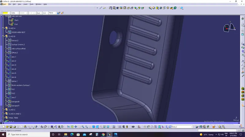
Class B surface
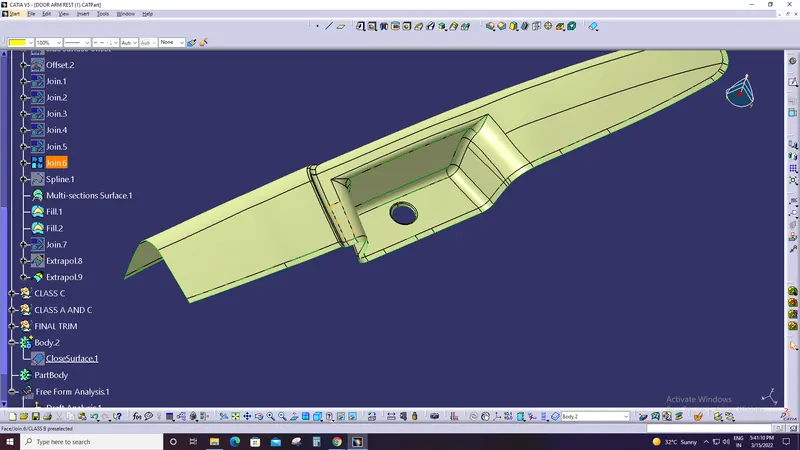
here we dont some improvement on the class b and joint with 0.003mm
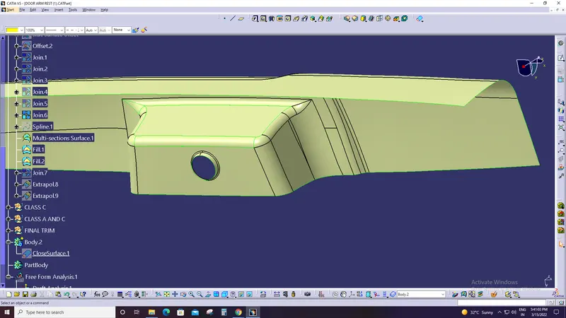
Class B surface was created from the class A surface using 'Extract/MultipleExtract' option.
Class B surface was offseted at a distance of 2.5 mm thickness from the class A surface. Fillets were applied after necessary calculations.
Class B surface (yellow) created along with the Class A surface (blue) are shown in the image.
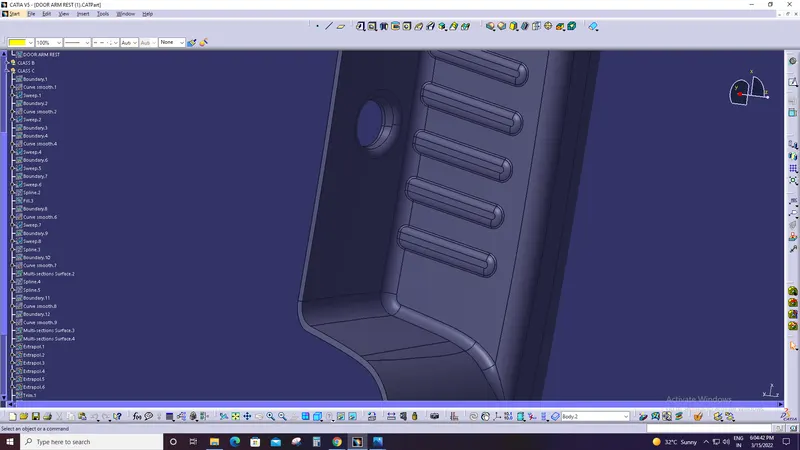
Class C surface
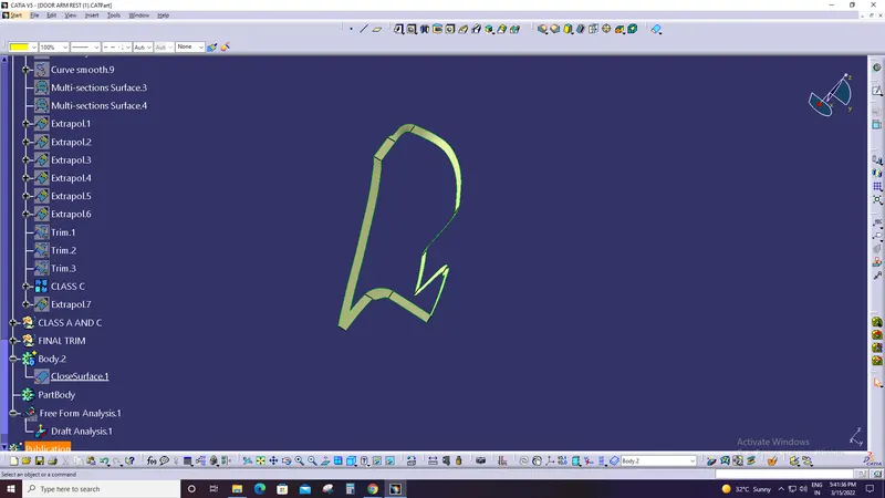
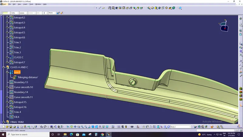
Class C surface was swept along the boundary of Class A using ' Sweep' option at an angle normal to the class A surface with respect
to the tooling axes. A nominal draft angle of 3 degree was applied. The Class C surface joined along with the Class A surface is shown
4. Closed surface creation
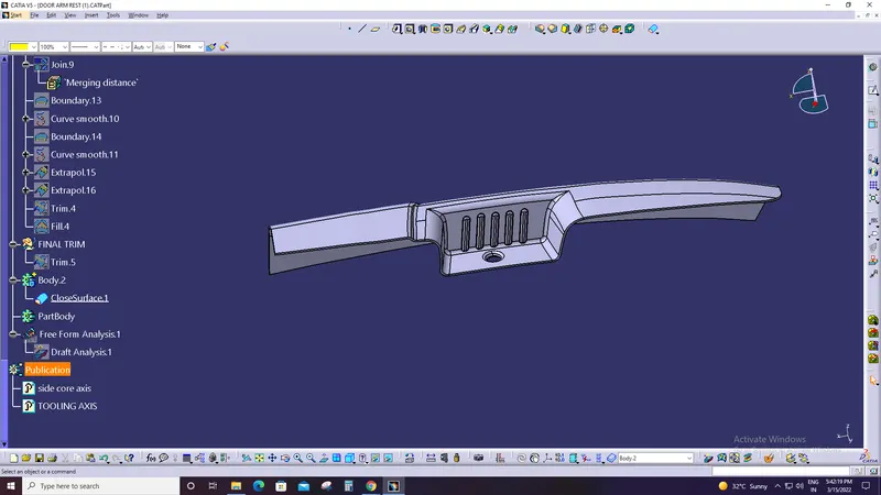
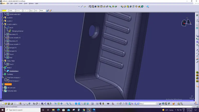
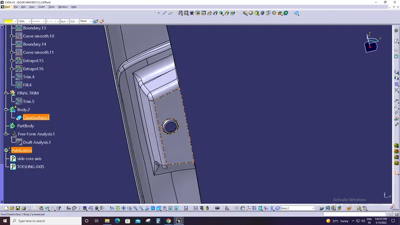
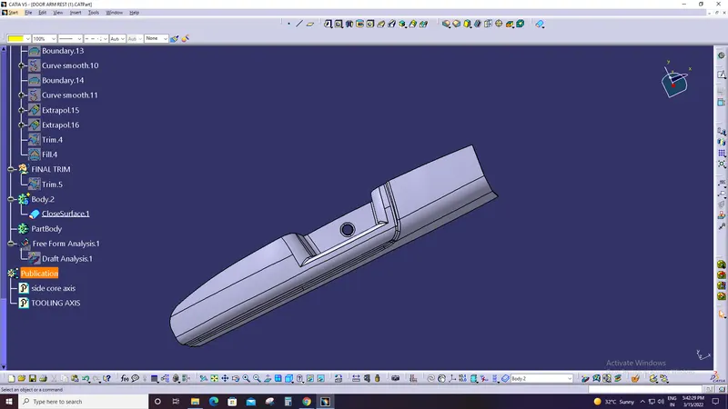
Here, Class A, Class B & Class C surfaces were joined together to form a single closed surface. Earlier we had already joined the Class
A surface with the Class C surface with a merging distance of less than 0.003mm.
Now we will trim the Class B surface with the joined class A & C Surfaces. Thus we will get a closed surface as shown below.
Then a part body was inserted and a closed body was created using part workbench.
5. Final Draft Analysis Result
TREE STRUCTURE