Door Arm Rest Week 8 Challenge
AIM:
The Aim of this project is to create Class B surface and Class B surface by using Class A surface and to create a Closed body by using all these surface. draft analysis has to check weather it satisfy the manufacturing conditions or not.
DRAFT ANGLE IN PLASTIC:
Draft is the providing angle or tapers on product feature such as walls, ribs, posts and bosses that lie parallel to the direction of release from thmold eases part ejection.
for doing the draft analysis, a tooling direction is required.
DRAFT ANALYSIS TOOL IN PLASTICS:
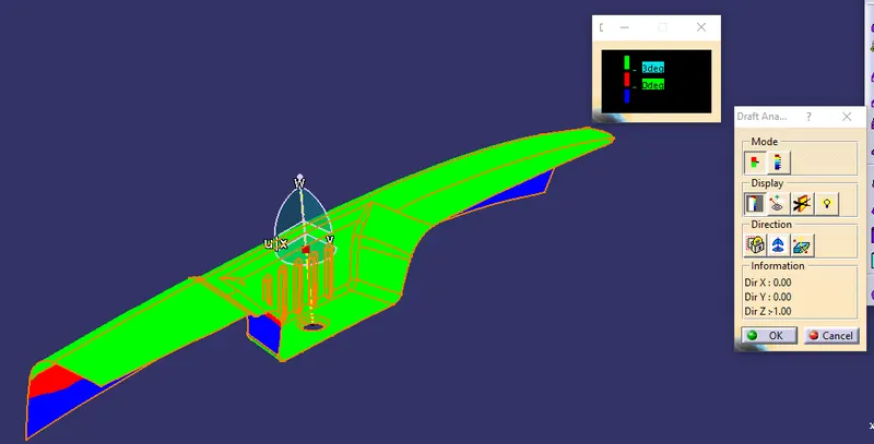
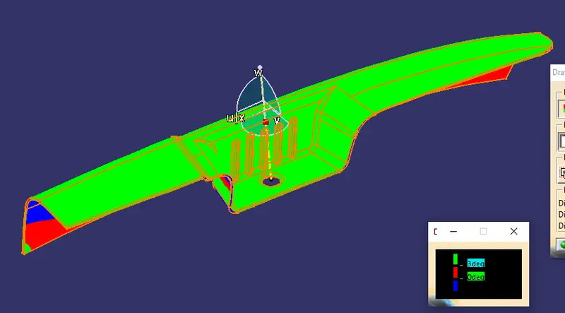
By using draft analysis tool, it identifies the zone (using colour code) and highlights the area which deviates from the specified values along a defined draft direction.
PROCEDURE FOR DRAFT ANALYSIS:
- Set the customised rendered style
- Select the draft analysis tool
- Adjust the draft direction to molding axis using compass
- Observe colour range
Green colour for draft angle less than 3 degrees
Red colour for draft angle less than 0 degrees
Blur colour for draft angle 0 to 3 degrees.
- 3 degrees is for nominal draft
- 0.5 degrees can be manufactured at ribs
- 7 degrees for textured faces
Steps involved in creating Tooling Axis:
1. creating tooling Axis along X direcion:
Create a mid point on the center and draw line along Z direction. It can be stated as Tooling axis along X direction.
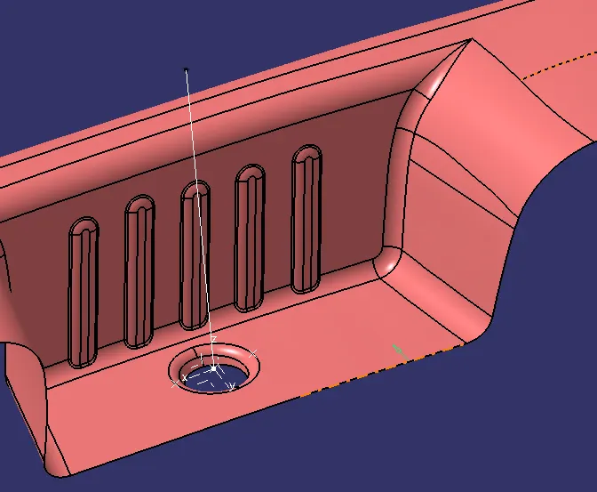
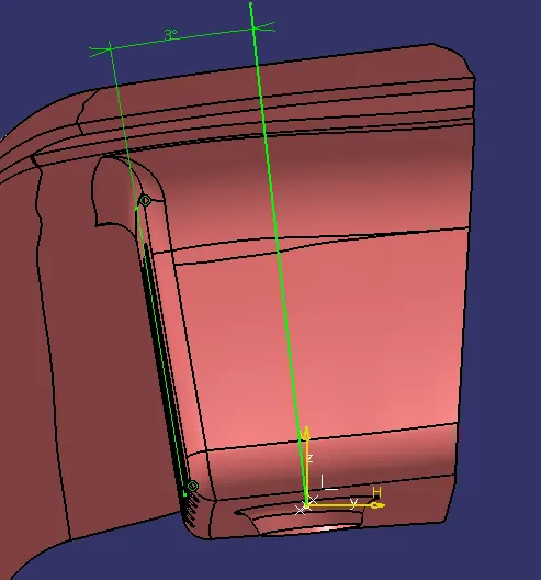
2. Creating Tooling axis along Y direction:
create axis system and intersect Class A surface and axis system along YZ direction.
make a possible line and draw aother line passing through orign with making an angle 3 degrees.
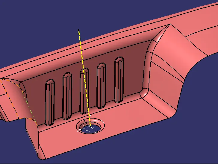
3. Create a bisecting line along the tooling axis on X direction and Y direction. this can be stated as Tooling axis.
STEPS INVOLVED TO CREATE CLOSED BODY BY USING CLASS A SURFACE:
Extract the main surface. extrapolate these surface until they intercect each other.
offset each other with 2.5mm length and trim it off.
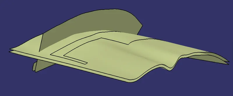
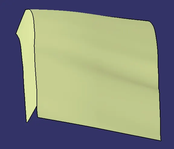
make edge fillet of required dimensions.
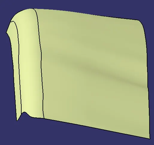
extract another 2 possible suface and extrapotae upto their intersection and trim it off.
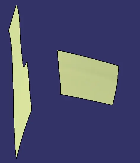
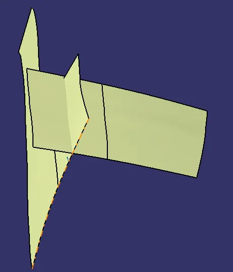
Offset each other and make edge fillet with required dimensions.
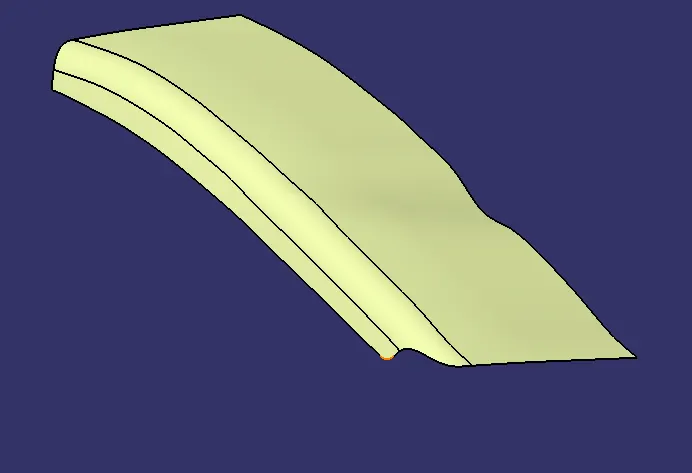
extract another 2 surfaces and offset and trim it off to get required surface.
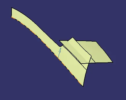
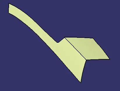
make edge fillet of required dimensioning.
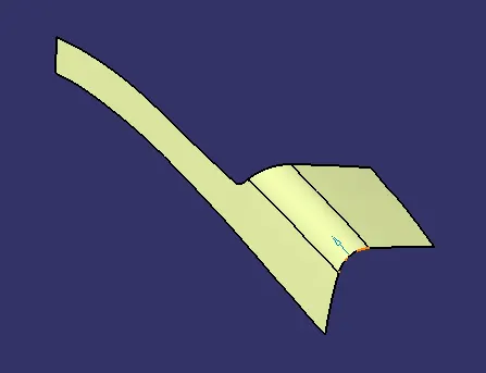
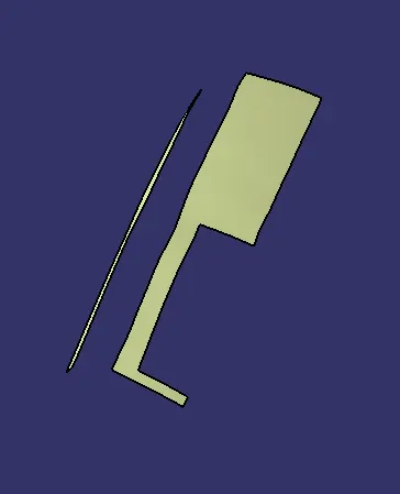
To join all the trimm surface, create a sketch as shown in figure and sweep surface as required.
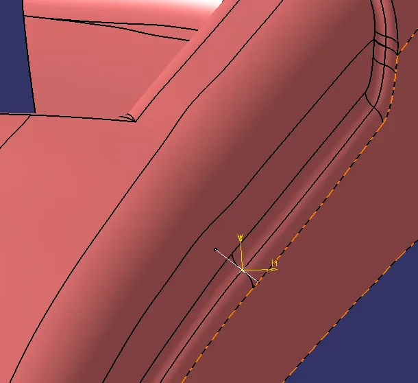
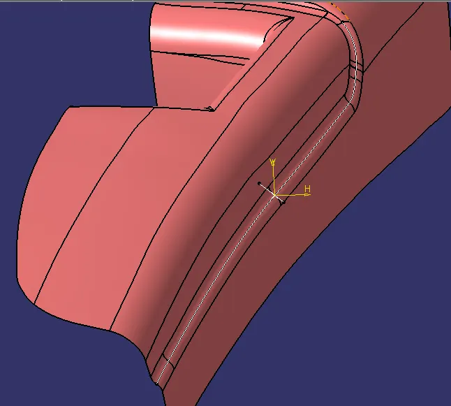
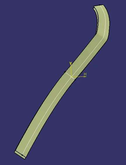
extract and un trim another surface. and join sweep and this off set surface.
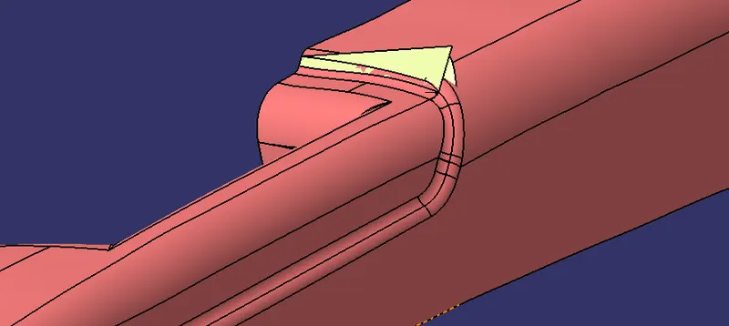
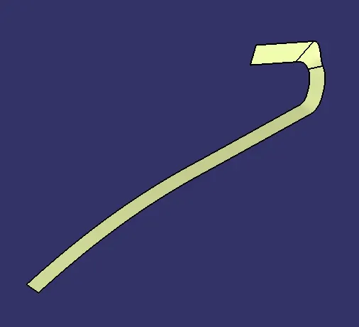
Join all the surfaces and give edge fillet to get the required B surface.
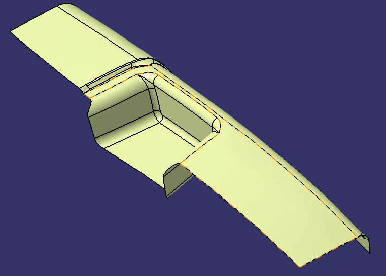
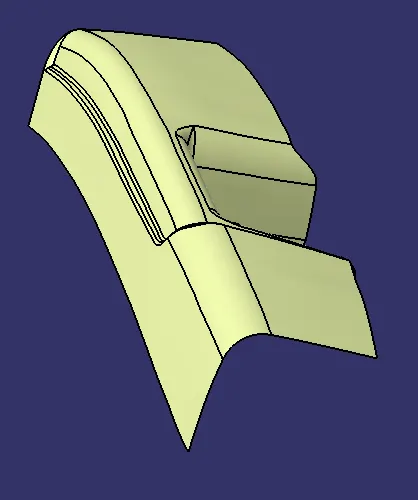
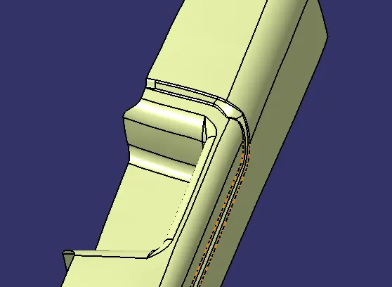
Creation of Class C surface.
Create a Boundry and sweep as per the required surface. and join the surface.
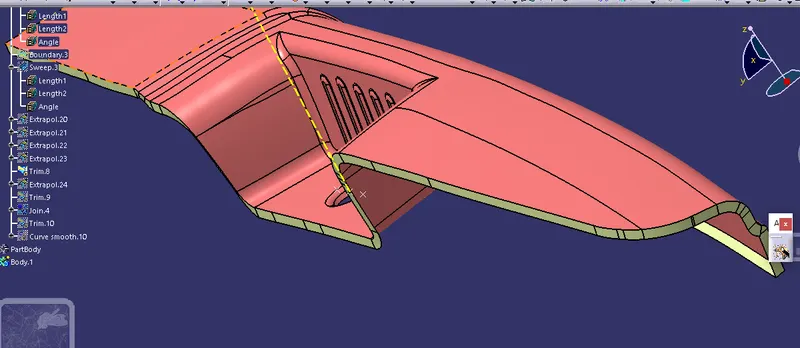
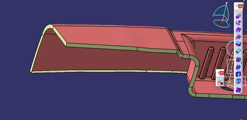
Now join The required surface (class B surface and Class A surface.
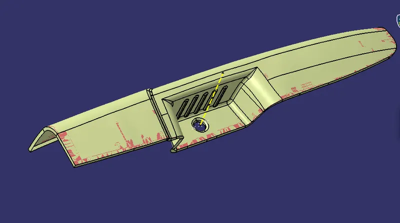
Now un hide B surface and trim All the surfaces to get a Closed surface.
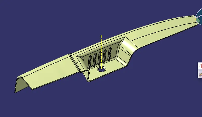
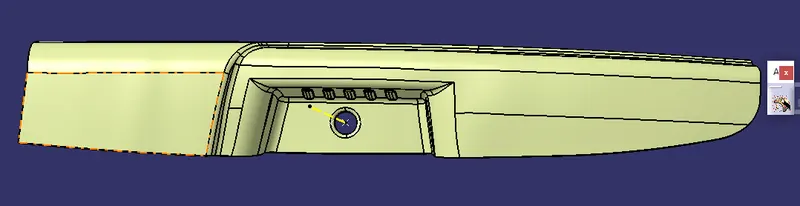
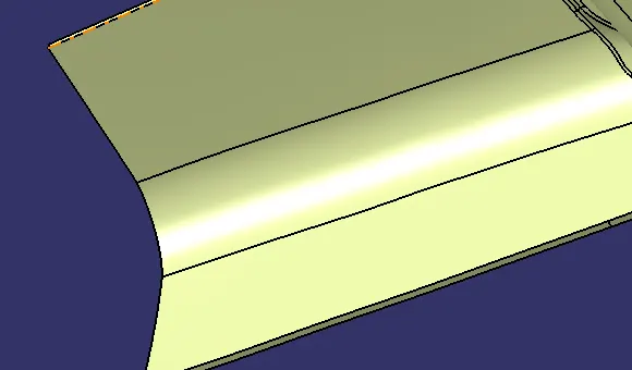
CLOSED SURFACE: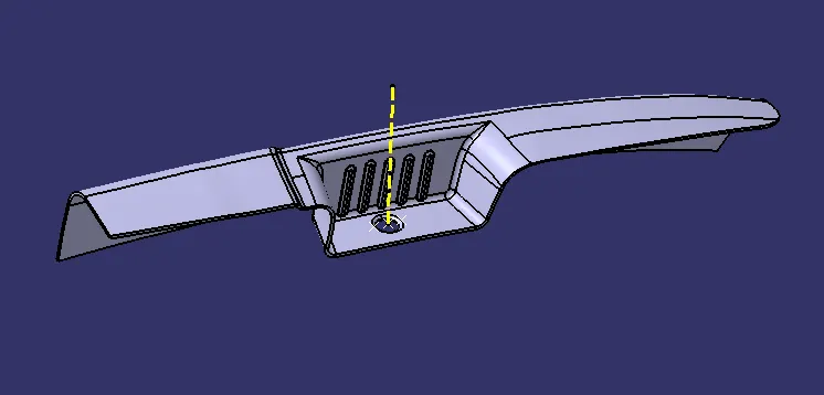
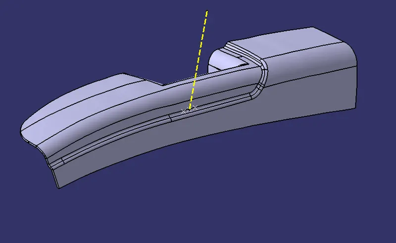
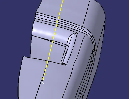
DRAFT ANALYSIS:
Draft analysis on Class A surface:
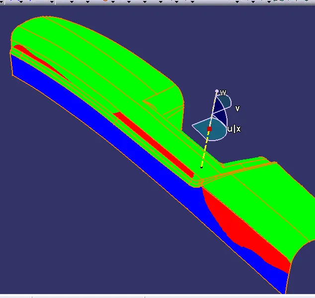
Draft analysis on Closed surface:
COLCLUSION:
1. Tooling axis has created
2. Draft analysis has done to check weather it satisfies the manufacturing condition for injection molding process or not.
3. Class B surface and Class C surface has created by using Class A surface.
4.Closed body has Created.
By observing and analysing the draft analysis it will not suitable for Injection molding process along the tooling axis in Z direction. due to ribs and curve shape along the base surface.
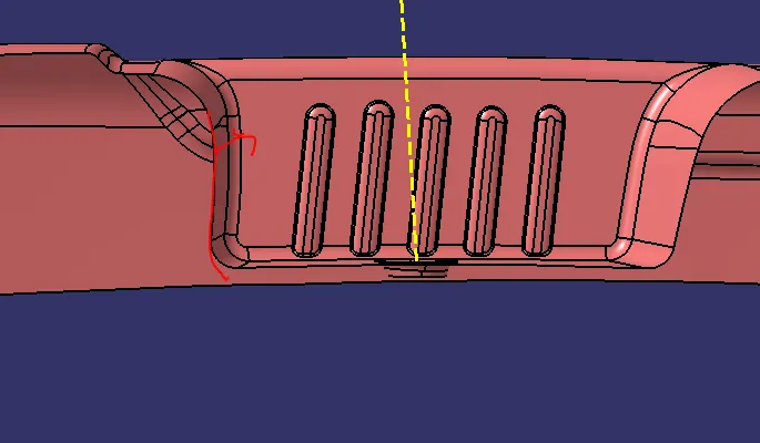
due to this curved surface, if we observe there is no draft angle. for this, draft angle remains positive and changed to negative. hence the Core dosent, come in linear way once it engaged due to ribs also. so that the given product is not suitable for injection molding process. but satisfies tiiling aling horizantal dorection.