Door Arm Rest Week 8 Challenge
HELLO SIR,
Door Arm Rest Week 8 Challenge
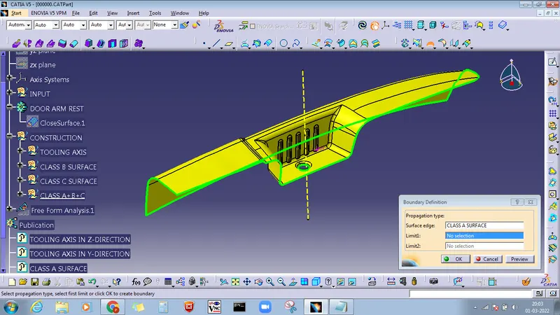
First, I check the connectivity of the (Class A) door arm model. Click on the join command & boundary command to check, and to ensure that there is no gap between the surfaces.
CREATION OF TOOLING AXIS
MAIN TOOLING AXIS
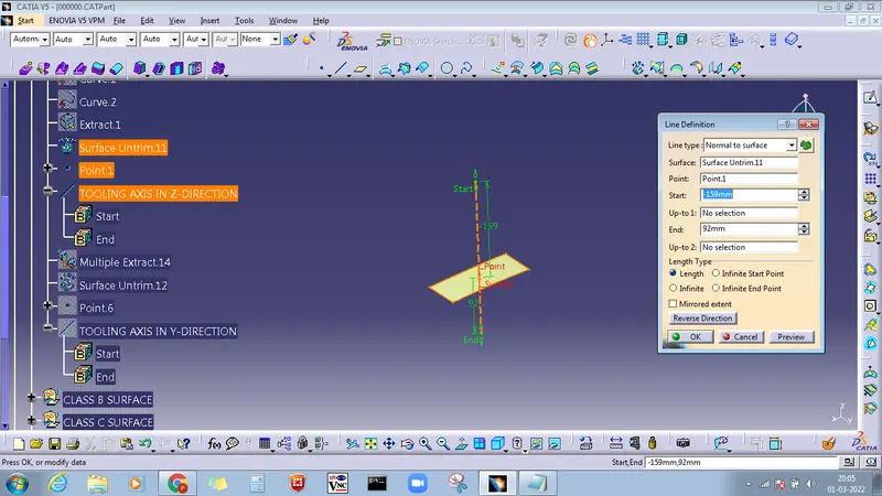
First of all, click the multiple Extract command to extract the base of the CLASS A surface, then create a point using the point command, and then use the line command to create a tooling axis.
SIDE CORE AXIS
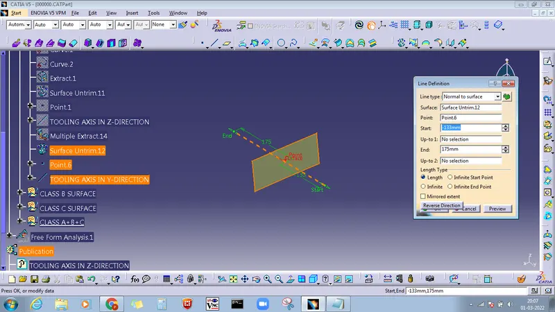
Go to multiple Extract command to extract the side of the CLASS A surface, then create a point using the point command and then use the line command to create a tooling axis.
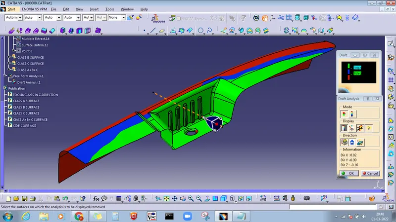
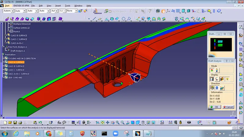
DRAFT ANALYSIS OF CLASS A SURFACE
MAIN TOOLING AXIS
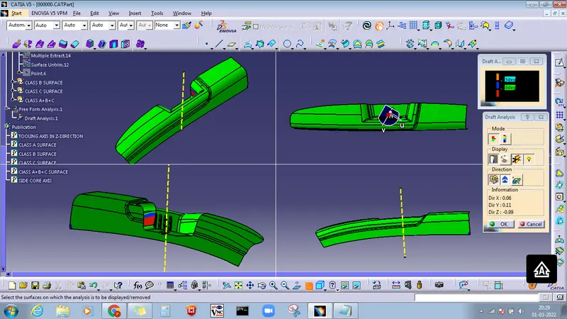
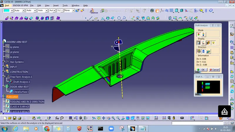
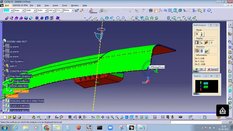
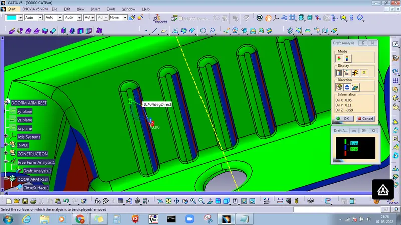
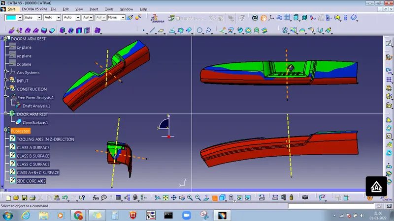
Draft analysis not clear at 3° in main tooling axis. some parts of the ribs and side surface are not cleared as indicated in blue color.
SIDE CORE AXIS
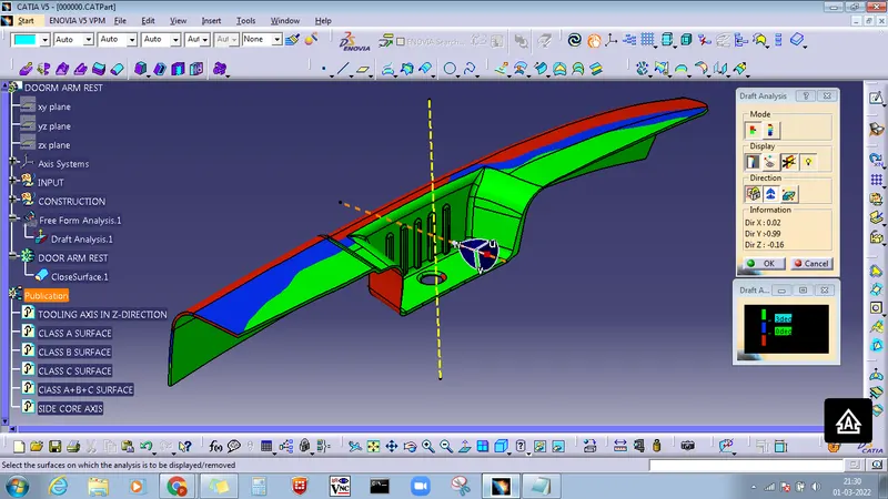
In this analysis, it is cleared at 3 degrees in the side core axis. all part features are clear but the hole is not removed in the side core axis.
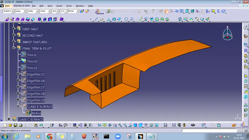
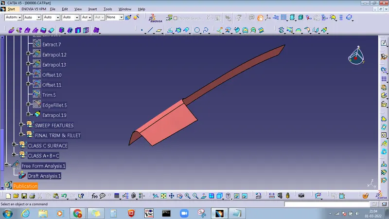
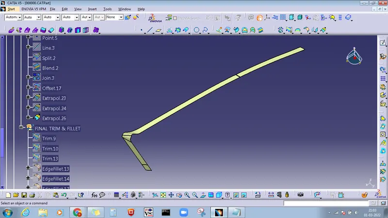
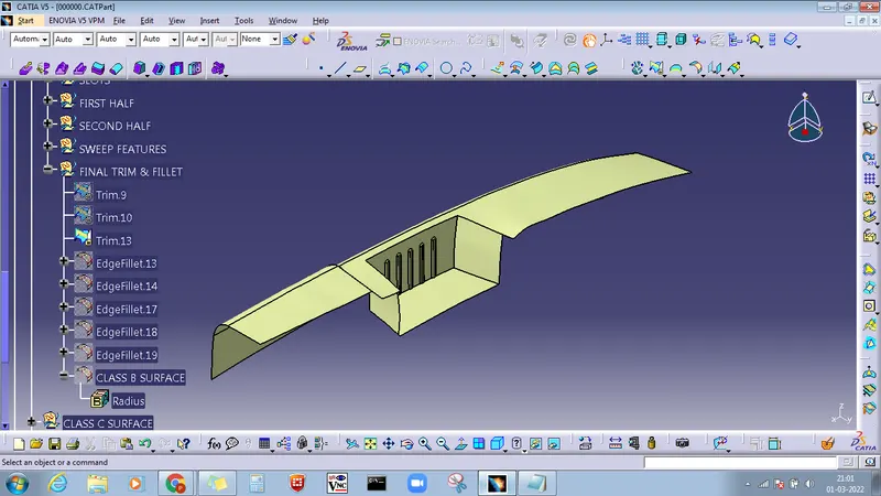
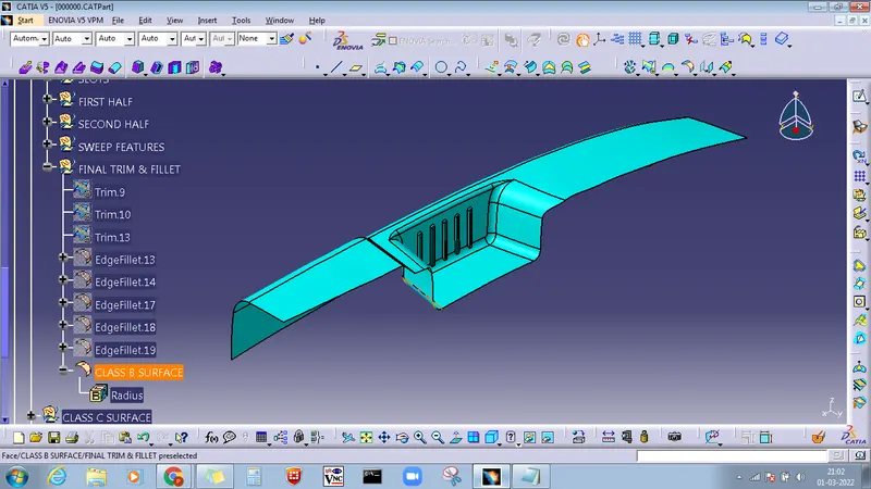
CLASS B SURFACE CREATION
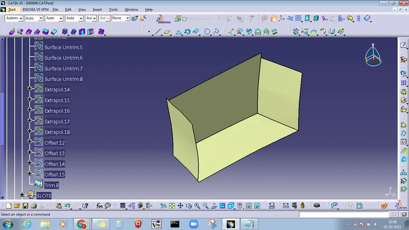
- first use the Extract command to extract the surfaces of class A.
- then Untrim the surface
- then if the surface is not intersecting then use Extrapolated command
- then, use the offset command to surfaces
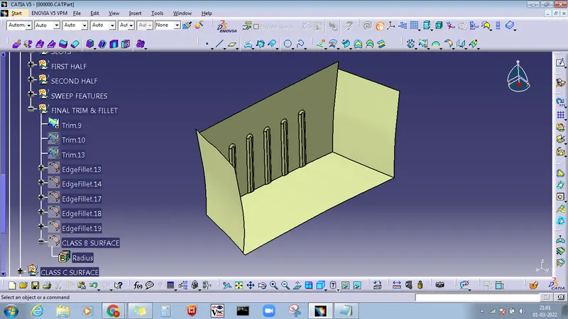
- then use the trim command to trim the unwanted surface.
- and finally, use fillet command to surfaces.
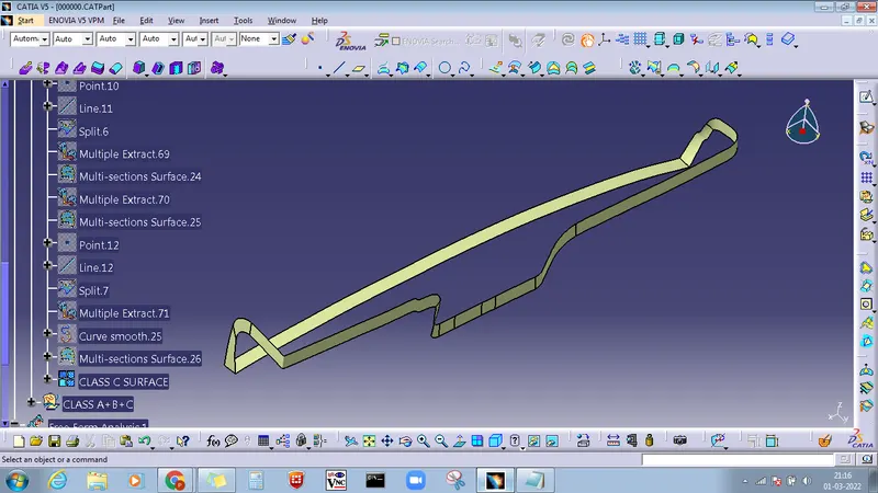
CLASS C SURFACE CREATION
Using the multiple extract command, smooth curve command, point command, line command, split command sweep command, and multi-section command to create c surface.
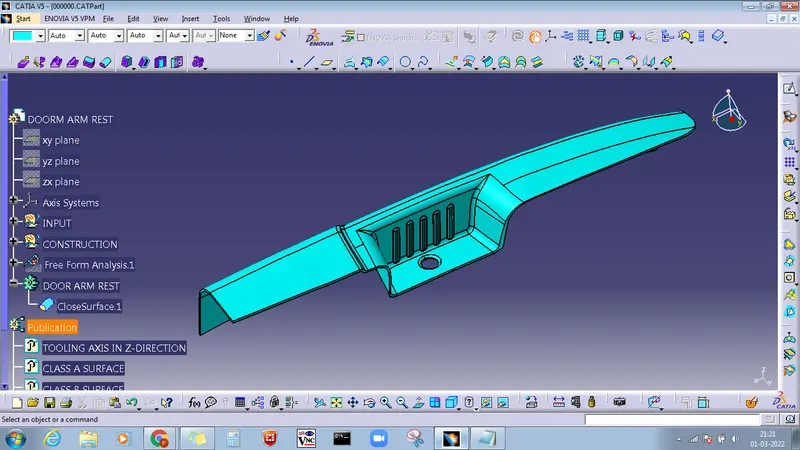
JOINING CLASS A+B+C SURFACE

After joining the Class A+B+C surface go to part design and solidify the component.
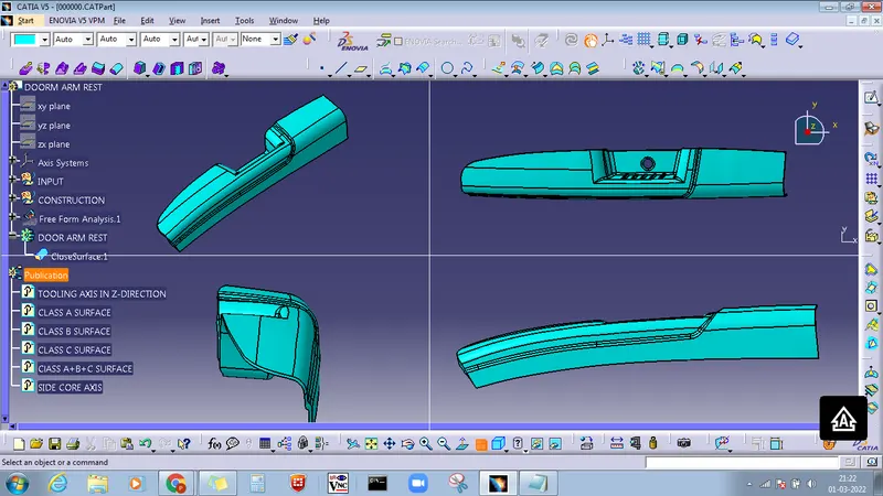
TOP, FRONT, SIDE, AND ISOMETRIC VIEW
DRAFT ANALYSIS OF DOOR ARMREST IN MAIN TOOLING AXIS
First, we have to customize the view parameter, I select the materials option, and go to the draft analysis command it will appear on the screen.
DRAFT ANALYSIS OF DOOR ARMREST IN THE SIDE CORE AXIS
THANKS