Door Arm Rest Week 8 Challenge
Project Title : DOOR ARM DESIGN
OBLECTIVE :
This report demonstrates the design of a Door Arm Rest an Automotive Plastic Components using industry principals such as Draft angles, Draft Analysis, Determining and implementing of tooling Axis, Class A, Class B, Class C surfaces and maintaining the thickness of the part at 2.5mm. The component is designed using Surface Design and Solid Design techniques in CAD package CATIA V5.
DRAFT :
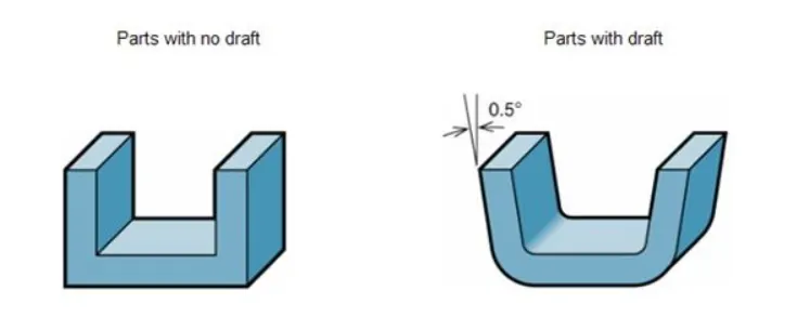
- Draft is an angular tapering given at the design stage to every Plastic Component that has to be manufactured.
- It is given in the direction of the Modal Movement.
- The draft allows the parts to release easily from the mold without creating friction between the surface of component and the core and cavity plates.
- When a Plastic component cool down inside the mold, the natural tendency of it is to shrink and attach to the core or cavity half.
- The movement of mold opening causes friction on the walls of the component as well as the core/cavity blocks.
- This reduces the life of the mold as well as the component itself.
- The component may also have rough surface finish as well as weak structure due to this.
- This problem can be solved by giving draft to the component.
- Most applications require minimum draft angles of around 0.5° to 1°, however 3° draft angles are widely accepted for cost saving purpose.
- 7° Draft angles are given to textured surface like Instrument Panels.
- Minimum possible draft angles are given to screw bosses, ribs and stiffeners due to their critical nature.
TOOLING AXIS :
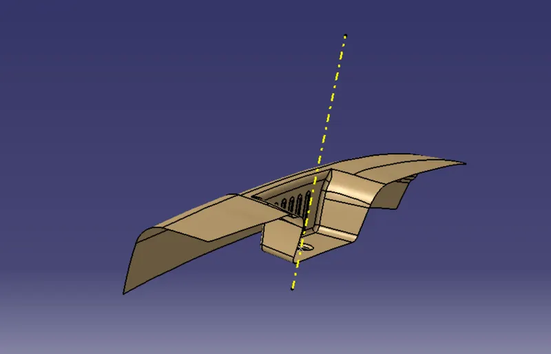
- Tooling Axis is the direction in which the Mold opens and closes. Part Drafts are generally given along this axis.
Class A surface :-
- In automotive design, a class A surface is any of a set of freeform surfaces of high efficiency and quality.
- It is the visible aesthetic surface of any automotive component.
- Class A surface refers to those surfaces which are visible and abide to the physical meaning, in a product.
- This classification is primarily used in the automotive and increasingly in consumer goods industry.
- It is a requirement where aesthetics has a significant contribution.
- For the reason, the exterior of automobiles is deemed Class-A.
Class-B Surface :-
- Class B surface are Engineering Surfaces which are invisible to the eyes or often on the back side of the Class A surface.
- It is mainly the thickness of the component or Class A.
- These surfaces need to be designed as per the Class A surface i.e., the continuity, thickness of the component, functionality etc should be maintained.
- These surfaces include the main engineering features such as Screw bosses, Ribs, Snaps, Stiffeners and fixations.
- B surfaces also do not contain any aesthetic styling content and textures since it is not visible to eyes.
Class- C Surface :-
- Class C surfaces are connectors between Class A and Class B surfaces.
- This surface connects both A and B surfaces along the tooling Axis.
- It contains the draft as per the design.
- It is basically the thickened surface between both A and B surface.
- Below Figure 6 shows Class A, B and C surfaces: Blue surface is Class A, Orange surface is Class B and Purple surfaces are Class C surfaces.
DOOR ARM REST DESIGN :
Procedure to be followed:
Step 1 : Design Check (Pre Check) on received Class A :-
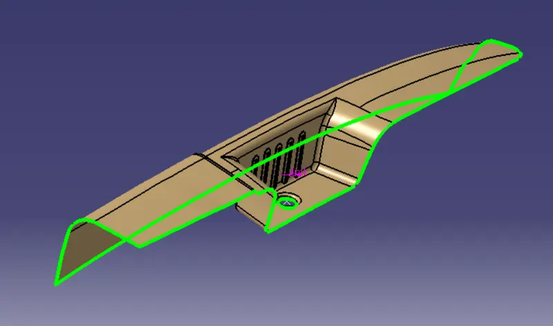
- After receiving the Class-A for the Coin Holder check for the connectivity of the surfaces on it.
- Use boundary operation and disassemble.
- Check for discontinuous Surface.
- The check is over if any discontinuities do not arise.
Step 2 : Determine the tooling Axis :-
- Identify faces which can potentially create problems while manufacturing.
- Surfaces at angles along a desired Tooling Axis.
- Extract a plain surface and create a point on its center for Axis system creation.
- In this case Z axis can be a possible Tooling Axis Direction.
Step 3 : Draft Analysis on Class A and Possible Creation of Side Tooling Axis :-
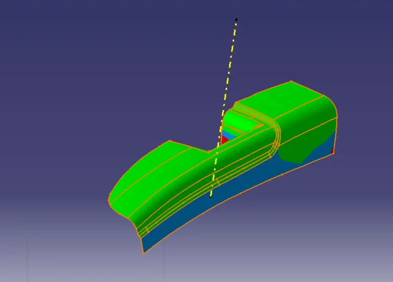
- Change View Mode Customization to Material mode.
- Go to INSERT--->ANALYSIS--->FEATURE DRAFT ANALYSIS and move the compass to the moving Axis.
- The input Class A also has walls having negative angle to the tooling axis.
- This can be an issue while manufacturing the component as it would be very difficult to draw from the molds.
- So, this design needs to consider Various Side Tooling Options.
Step 4 : Class B Surface Creation :-
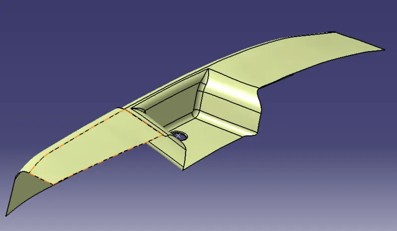
- Extract The Class A Surface for example the Bin Base.
- Untrim it to obtain a continuous surface.
- Extrapolate the obtained surface to a value such that it passes the class A bin.
- Offset the Surface to value 2.5 on B Side which is downwards in this as shown in below Figure.
- Use similar options for Side Walls and Upper Surface.
- Use Extrapolate option only on required Direction to obtain the Surface trims.
- Use fillets so as to maintain Wall Thickness to 2.5mm.
- Create Fillets while maintain the part thickness of 2.5mm between the Class A and Class B surfaces.
- The Value of fillet is given by the equation (B Surface fillet = A Surface fillet +(or) – Thickness of the part).
- The sign + or –must be decided so as to maintain the part thickness which in this case is 2.5mm.
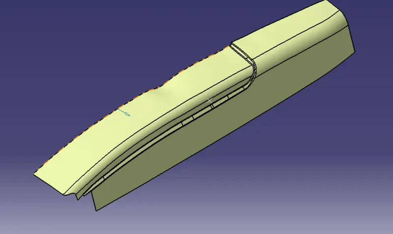
- To create a Connecting Surface for the Class B Create a Axis System on the Extract Point.
- Intersect the Class A with the YZ plane.
- Create a Line Tangent to the Fillets on the Intersection.
- Use Sweep operation along the Line for the Smooth Curve.
- The obtained sweep is shown in Figure.
- Trim the Connectored with other pre created B surfaces.
- Make adjustments as per requirement.
“B Surface Trims”
- Create appropriate Fillets as per the rules.
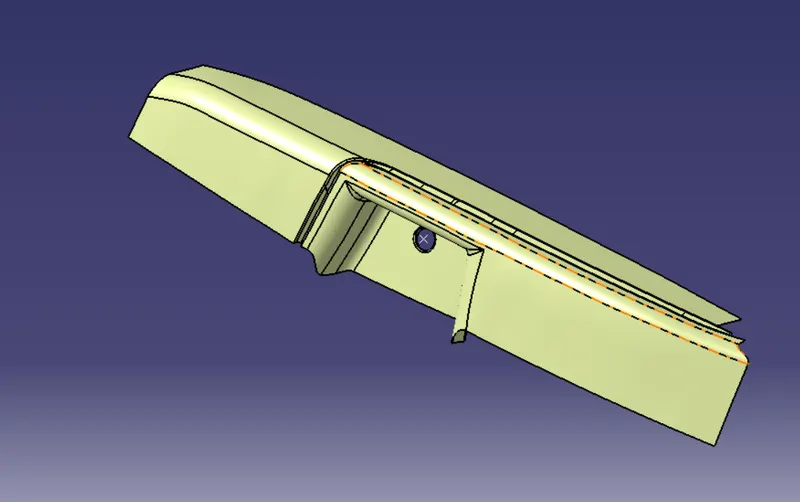
- Create features aesthetic Ribs on B Surface.
- Create the Hole in Bin offset to that on the Class A Surface.
- The Final B Surface Obtained is shown in Figure.
Step 5 : Class C Surface Creation :-
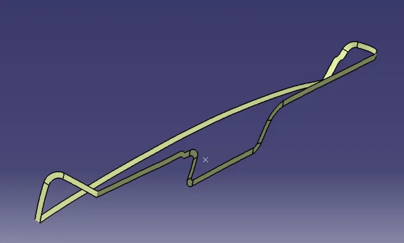
- Extract Class A boundary and convert to Smooth Curve.
- Sweep this curve at 90 degrees to the Class A.
- Sweep value should be greater than the Thickness required for part.
- The obtained sweep.
- Join the Class A Surface with the Class C surface to create a single surface entity.
- The obtained surface is shown in Figure.
Step 6 : Enclosed Surface Creation :-
- Trim the obtained surface with Class B surface.
- Make Slight Adjustments by extrapolating small values and trimming to obtain a final Enclosed Surface.
- The final Enclosed Surface Obtained.
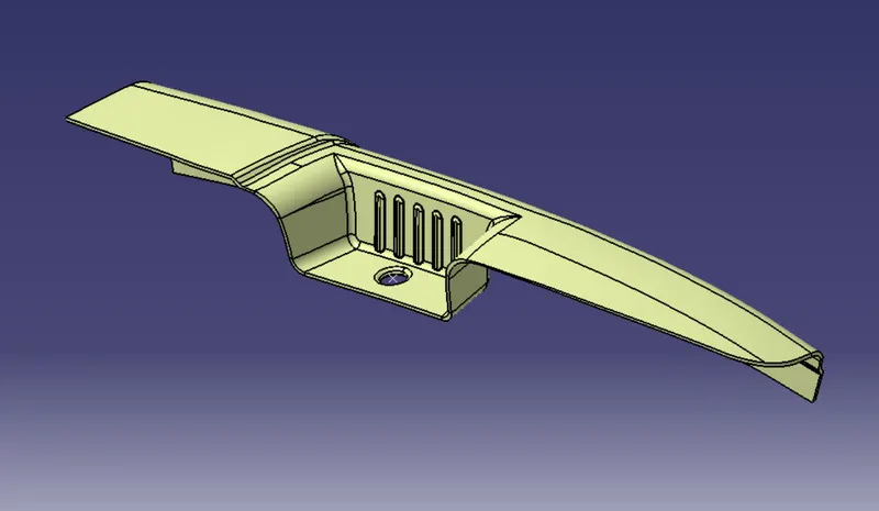
Closed Surface:
Make the final trim to solid part using close surface.
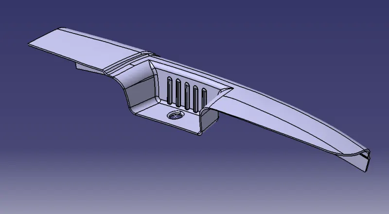
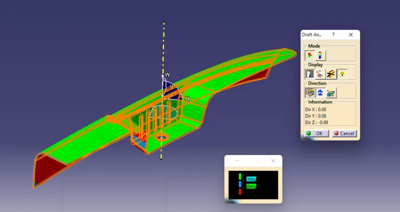
Step 7 : Perform Draft Analysis on Final Enclosed Surface :-
- Change View Mode Customization to Material mode.
- Go to INSERT---> ANALYSIS---> FEATURE DRAFT ANALYSIS and move the compass to the Main Tooling Axis.
- Change the range to 3°. Apply the settings as shown if Figure.
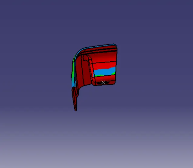
Draft Analysis by Side Core Tooling Axis :-
Perform Draft Analysis along other Side Tooling Axis.
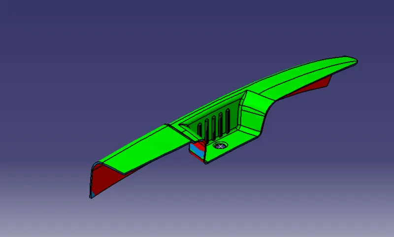
VIEWS OF THE DOOR ARM REST :
- Front View
- Back View
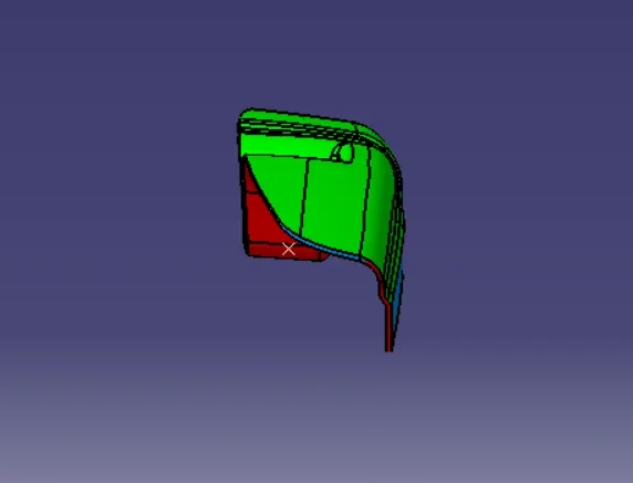
- Left View
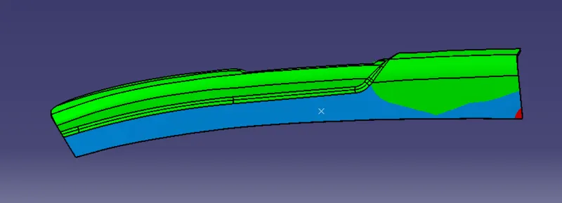
- Right View
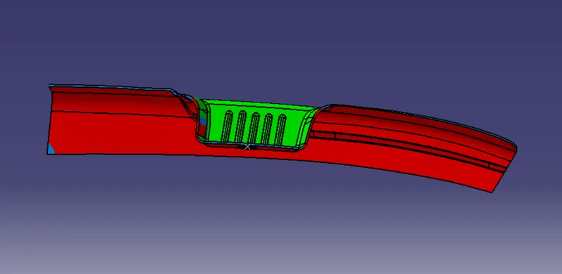
- Top View
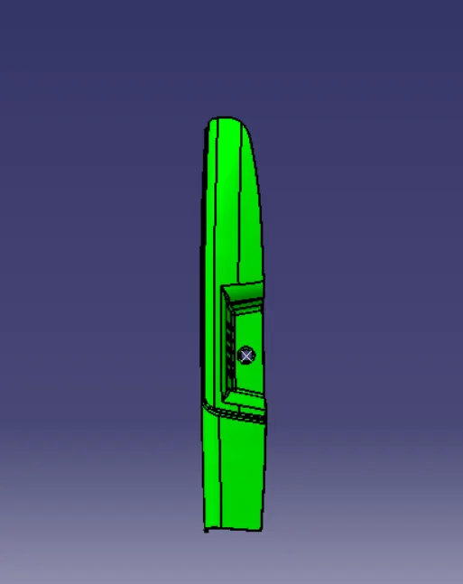
- Bottom View
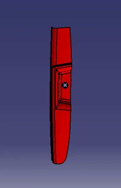
- Isometric View
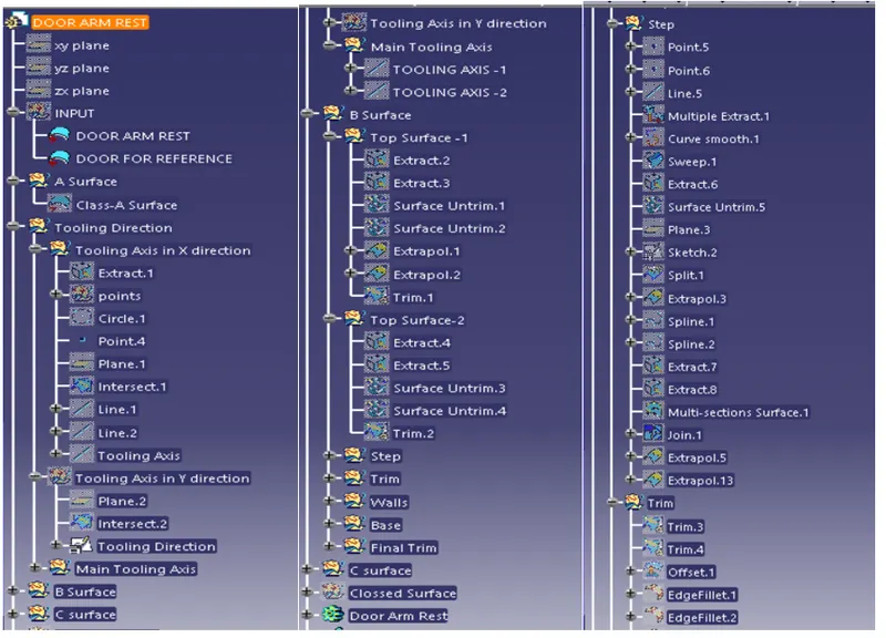
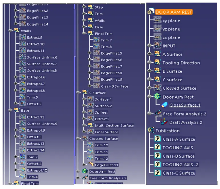
TREE STRUCTURE :
CONCLUSION :
The Design of Automotive Plastic Component – Door Arm Rest from Class A as input is completed using concepts of Draft Angles, Draft Analysis, Determining and implementing of Tooling Axis, Side core Axis, Class A, Class B, Class C surfaces and Maintaining the Thickness of the part at 2.5mm and finally converting the enclosed Surface into solid Part.