Photo Realistic Rendering
MODELING AND RENDERING OF AMERICAN CHOPPER BY USING SOLIDWORKS
1) INTRODUCTION :
Solidworks is used to develop mechatronics systems from beginning to end. At the initial stage, the software is used for Planning, Visual Ideation, modeling, feasibilly assessment, Prototyping, and project management. The software is then used for design and building of mechanical, electrical, and software elements. In this project report contains a detailed explanation of designing an american chopper from beginning to end of the modeling and assemply. In this report is to learn how to create the models using different tools such as Sketch, Extrude, Cut Extrude, Mirror, Fillet, Lofted Boss/Base, Trim Entities, Revolve, Appearance, etc.
2) OBJECTIVE :
The main objective of this project is understanding the different tools and commands used to design the american chopper in solidworks.
The following steps were designing the american choper:
- Design of the individual components
- Assembly of the American chopper
- Application of decals, setting up the scene, lights and cameras
- Final rendering of the American chopper
3) COMMANDS USED IN SOLIDWORKS :
SKETCH :
- Sketch is the two dimensional representation of the model with respect to the plane/view from the outside of the model. In solidworks there are different sketch options available to create a sketch. These are known as Entities in solidworks. Commands are available in solidworks such as line, Cricle, Arc, Spline, Rectangle, Etc.
OFFSET :
- An offset Entities relation is created between the new sketch entity and the selected entity. If the original entity changes, the new entity updates to maintain the offset. To create a offset click on Offset Entities (sketch toolbar) or click Tools > sketch tool > Offset Entities.
EXTRUDE BOSS/BASE :
- Extrude command is used to conversion the 2D sketch into 3D model. To create Extrude Boss/Base
FILLET :
- Fillet/Round created a rounded internal or external face on the part. you can fillet all edges of a face, selected sets of faces, selected edges, or edge loops
LOFTED BOSS/BASE :
- Lofted Boss/Base is used to create or add material two or more profile to create a solid feature.
SWEPT BOSS/BASE :
- Swept a closed profile along open or closed path to create a solid feature
REVOLVE BOSS/BASE :
- To create a revolve feature : create a sketch that contains one or more profiles and a centerline, line, or edge to use as the axis around which the feature revolve. Click one of the following revolve tools.
EXTRUDE CUT :
- Extrude cut is another cool feature which helps to remove materials from the 3D model. It can cut in both directions and mainly used for creating hole, channels, slots etc.
DOME :
- Select one or more planar or non-planar faces. You can apply domes to faces whose centroid lies outside the face. This allows you to apply dome to irregularly shaped contours.
SPLIT :
- The split tool is used to project an entity (sketch, solid, surface, face, plane, or surface spline) onto other surfaces or curved/planar faces. You are also able to split face on multiple bodies with one command.
TRIM ENTITES :
- Select the trim type based on the entities you want to trim or extend. Trim one or more sketch entities to the nearest intersecting entity as you drag the pointer, and cross the entity
MIRROR :
- There are two mirror function available in while working with 2D sketching, mirror entities and dynamic mirror. Both allow you to mirror parts of a sketch about a straight line.
- MIRROR ENTITIES : The mirror entities feature can be found under the 'sketch' tab in the command manager or in tools > sketch tools > mirror
- DYNAMIC MIRROR : The dynamic mirror function, found in tools > sketch tools > dynamic mirror, is similar to mirror entites however the line or lines to mirror about are selected beforehand then anything draw in the sketch will be mirrored dynamically.
COMBINE :
- Combine is the type of feature available in solidworks to manually combine the two bodies.
SHELL :
- The shell feature hollows out the inside of the solid, leaving a shell of a specified wall thickness. It lets you specify a surface or surface that you want to remove from the shell.
CHAMFER :
- The chamfer tool is used to create a beveled feature on selected edges, faces, or a vertex. To create a chamfer : Click Chamfer (Features toolbar) or Insert > Features > Chamfer.
CIRCULAR PATTERN :
- The circular Pattern command is used for to create multiple instances of one or more feature that you can space uniformly around an axis.
LINEAR PATTERN :
- The linear pattern command is used to drive feature, faces, or bodies in a linear direction. This feature helps save time by cutting down the repetive movements of adding a bunch of holes or other forms of geometry.
APPEARANCES :
- An appearance defines the visual properties of a model, including colour and texture. Appearences do not affect physical properties, which are defined by materials. Every material is assigned a default appeaarance that emulates the look of the material.
LOFTED SURFACE :
- Loft surfaces are surfaces generated by multiple 3D Curves or existing edges creates a smooth tangency between the selected curves.
SWEPT SURFACES :
- swept surfaces are surfaces that are generated from a section curve positioned along a path.
FILLED SURFACE :
- The fillet surface feature constructs a surface patch with any number of sides, within a boundery defined by existing model edges, sketches, or curves, including composite curves.
SURFACE TRIM :
- Surface trim command is used to cut unwanted material from surface, and provides two modes : Standarad and Mutual.
EXTEND SURFACE :
- The command is used to extend the edges, multiple edges or the face on surface, based on end condition and extension type.
SURFACE KNIT :
- Surface knit is used to combines two or more adjacent, non-intersecting surface together.
4) DESIGN METHODOLOGY :
- Transmission Belt
- Kick Stand
- Chain
- Front Fender
- Rear Fender
- Pedal
- Front Wheel
- Rear Wheel
- Oli Tank
- Chassis
- Engine
- Front Fork
- Gas Tank
1-TRANSMISSION BELT :
Belts are mechanical used for power transmisson engine to gear box. They are loops of flexible materials used to mechanically connet several rotating shafts.
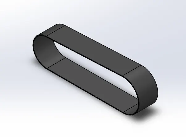
Figure: 4.1.1 Transmission Belt
FEATURES USED :
- Sketch
- Extrude Boss/Base
- Fillet
- Offset
- Appearances
The procedure to create a model of Transmission Belt :
- First, Open the Solidworks. Then, click on the new part to start modelling.
- Then, slelect the front plane to start the sketch.
- The 2D sketch is created in the front plane by giving dimension length between centers of two arcs, relations to fully define a sketch. while sketching, the offset command is used to duplicate the sketch to 3.5mm distance.
- After this process, the sketch is closed. Then, the extrude command is used to convert a 2D sketch into a 3D model with 88mm.
- Then, the fillet is given to the belt as per the requirements. The model of the transmission belt is created.
- Appearance of the part is change to rubber matte
- The model is saved with the name of Transmission Belt.
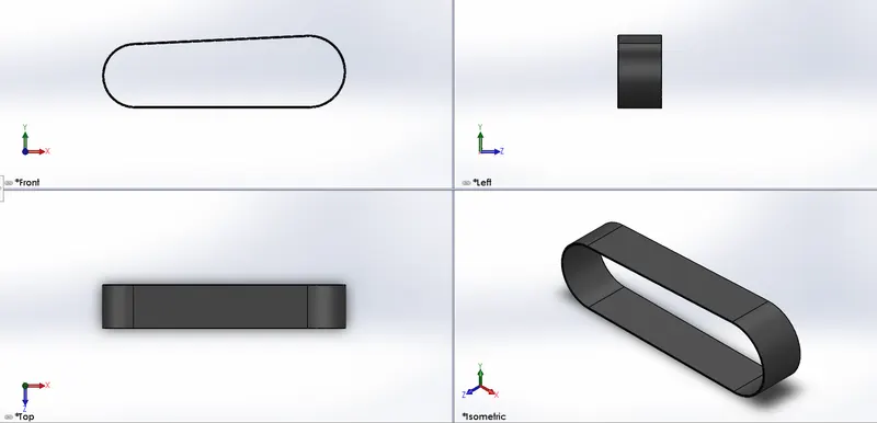
Figure: 4.1.2 Overall views of Transmission Belt
2-KICK STAND :
The KICK STAND is used to support the chopper when its rest, it is also known as side stand.
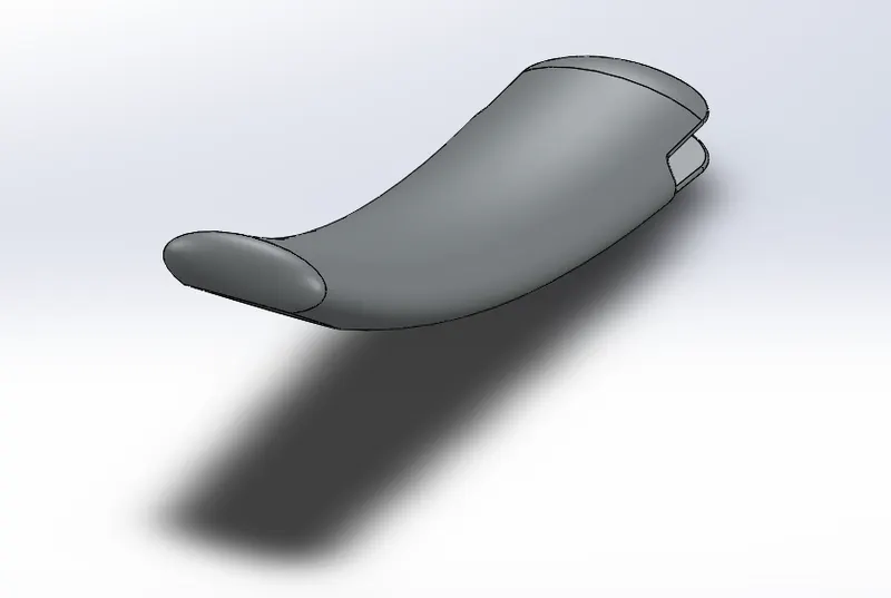
Figure: 4.2.1 Kick Stand
FEATURES USED :
- Lofted Boss/Base
- Dome
- Extrude Cut
- Split
- Extrude Boss/Base
- Fillet
- Appearances
The procedure to create a model of Kick Stand :
- Open the solidworks. Then, click on the new to start modeling.
- Then, create a sketch by selecting front plane
- The 2D sketch is created in the front plane by giving it dimensions, relation to fully define a sketch. While sketching we used the spline and trim commands.
- Create a new plane by selecting the spline and the ellipse are drawn in the new plane as per the requirement.
- Then the loft command is used to create a loft for the kickstand
- The extrude cut command is used to cut the parts which are not required for the stand.
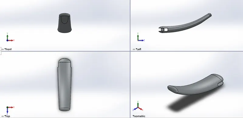
Figure: 4.2.2 Overall views of kick stand
3-CHAIN :
Chain is used to transmit the power from the engine to the Rear Wheel. Chain is made of steel. it passes over toothed member known as sprocket.
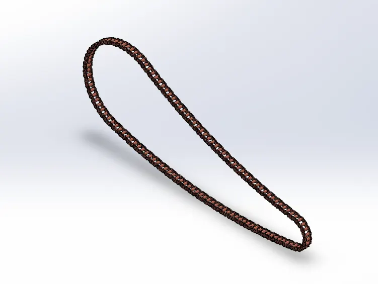
Figure: 4.3.1 Chain
FEATURES USED :
- Extruded Boss/Base
- Linear Pattern
- Fillet
- Mirror
- Combine
- Blocks
- Appearances
The Procedure to create a model of chain :
- Open the Solidworks. Then, click on the new to start modeling.
- The 2D sketch is created by using three point arc and tangent relations between the arc using the given dimensions on front plane.
- Then, create two throwaway sketches which are used to create the inside and outside links of the chain.
- Create a block and save the two throwaway sketches of inside and outside of chain link by using block command.
- Insert the blocks of chain links by selecting front plane and make coincident relation between the main sketch and chain links.
- Extrude the throwaway sketches of chain links by using the Extrude Boss/Base command and connecting pins are created using the same sketch.
- The create chain links are pins are then populated on the main sketch using the linear pattern and circular pattern features.
- All the chain link plates are then mirrored on the front plane.
- Combine the all the components of the chain as a single part by using combine feature.
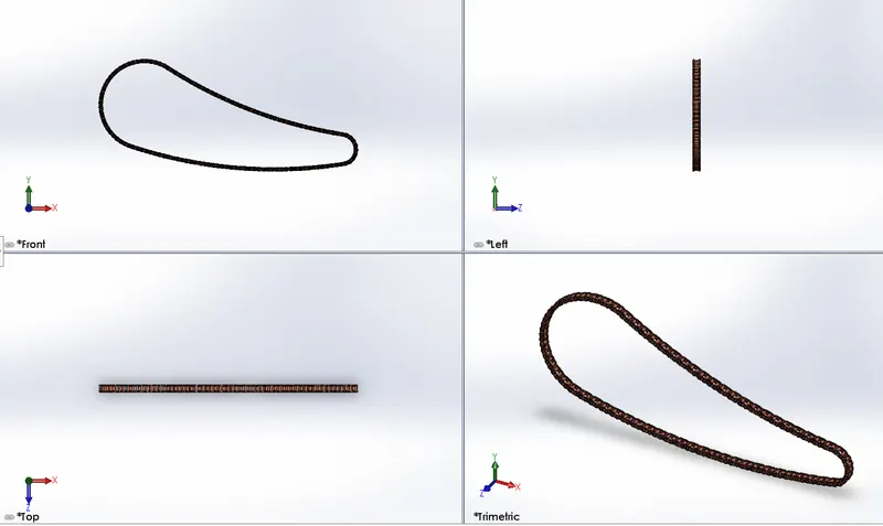
Figure: 4.3.2 Overall Views of Chain
4-FRONT FENDER :
It is the covering plate of the front wheel.
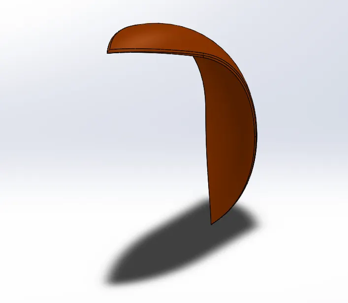
Figure: 4.4.1 Front Fender
FEATURES USED :
- Revolve Boss/Base
- Split
- Fillet
The Procedure to create a model of front fender :
- Open the Solidworks. Then, click on the new to start modeling.
- 2D sketch is created by using three point arc and offset it meet the thickness of the fender on front plane.
- Create an axis at the origin and revolve the sketch by using revolve Boss/Base command.
- Two different sketches are created in the Top and Right planes to cut the front fender in to required shape.
- Fillets are created on the sharp edges of the fender.
- Siena (car painted) appearace is applied.
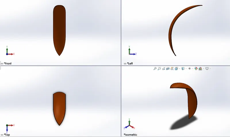
Figure: 4.4.2 Overall Views of Front Fender
5-REAR FENDER :
It is semi covering plate for the rear wheel.
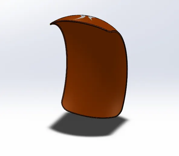
Figure: 4.5.1 Rear Fender
FEATURES USED :
- Revolve Boss/Base
- Split
- Fillet
The Procedure to create a model of rear fender :
- Open the Solidworks. Then, click on the new to start modeling.
- 2D sketch is created by using three point arc and offset it meet the thickness of the fender on front plane.
- Create an axis at the origin and revolve the sketch by using revolve Boss/Base command.
- Fillets are created on the sharp edges of the fender.
- Siena (car painted) appearace is applied.
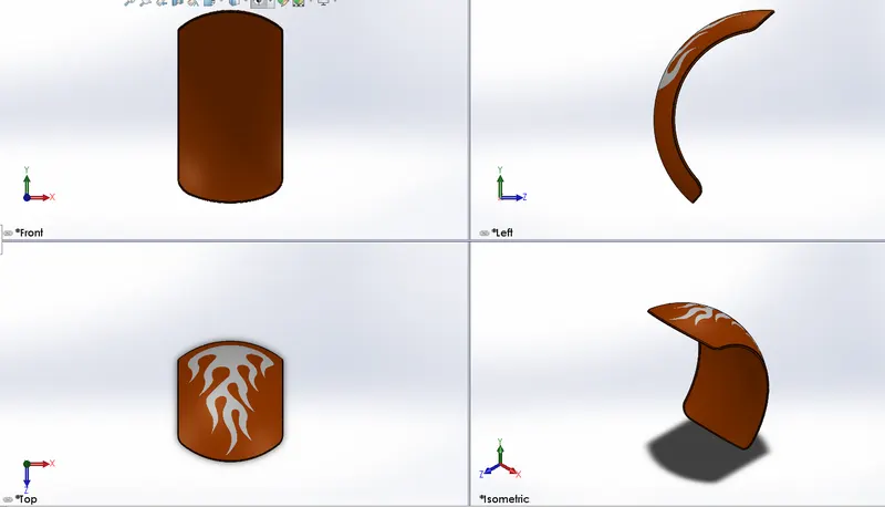
Figure: 4.5.2 Overall views of Rear Fender
6-PEDAL :
Pedal is used for motorcycle where the foot of rider rests and place wher the gear and brakes are available for applying comfortably to the rider.
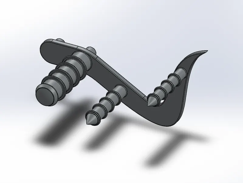
Figure: 4.6.1 Pedal
FEATURES USED :
- Extruded Boss/Base
- Revolve Boss/Base
- Dome
- Linear Pattern
- Chamfer
- Fillet
The Procedure to Create a Model of Pedal :
- Open the solidworks. Then,click on the new to start modeling.
- 2D sketch is created in the front plane by given dimensions, relations is fully define a sketch. While sketching we used the spline and sketch fillet commands.
- Extrude the circles sketchs for foot rest and attachments to the chassis.
- Fillet the sharp edges and create linear patterrns produce the ring profiles on the pedal.
- Chromium steel appearance is applied.
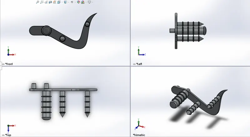
Figure: 4.6.2 Overall views of Pedal
7-FRONT WHEEL :
Front wheel is rotating part. It is circular frame of hard material. Wheels are usually used in pair, connected by a rod of metal known as an axle. It is guide the according to the movement of the front fork ass desired by the rider
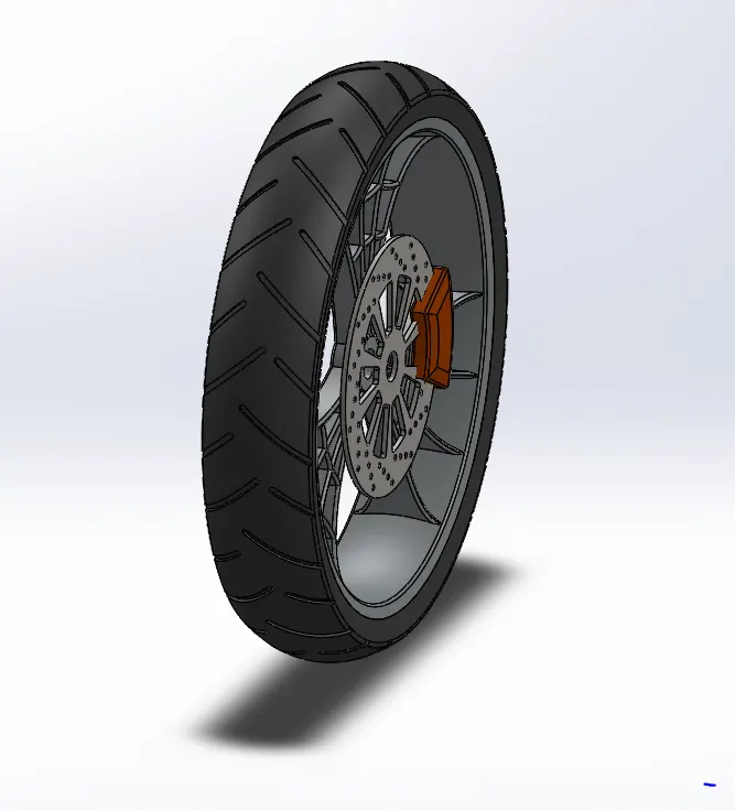
Figure: 4.7.1 Front wheel
FEATURES USED :
- Revolve Boss/Base
- Extruded Boss/Base
- Extruded cut
- Revolve cut
- Circular Pattern
- Trim
- Fillet Entities
- Combine
- Chamfer
The Procedure to Create a Model of Front Wheel :
- Open the Solidworks. Then, click on the new to start modeling.
FOR RIM :
- 2D sketch is created on front plane by given dimensions, relations is fully define a sketch. While Sketching we used the three point arc, spline and line commands.
- The revolved extruded using an imaginary axis at the origin. A spider wed design of the rim is created on the front plane and extruded using mid plane extrude feature.
- Add the spider web is circular patterned to requred numbers and combine the spokes and rim by using combine features to form a single body.
- Chromium plate appearance is applied.
FOR ROTOR :
- Create a circle sketch on the front and extrude it to the required dimension.
- Create the necessary holes using circular pattern.
- Chromium plate appearance is applied
FOR CALIPER :
- A sketch is created by using circle and lines and remove the unwanted skecth by using trim command.
- Extrude the 2D sketch of mid plane extrude the caliper profile.
- Create a chamfer on front and back face of the caliper and make a fillet of sharp edges.
- Siena (car Painted) appearance is applied
FOR TIRE :
- A 2D sketch is created converting entities of the rim on front plane. While sketching line and three point commands.
- Create a revolve the selecting the sketch by using the Revolve Boss/Base feature.
- Create a profiles on the outer surface of tire for grip.
- Matte rubber appearance is applied.
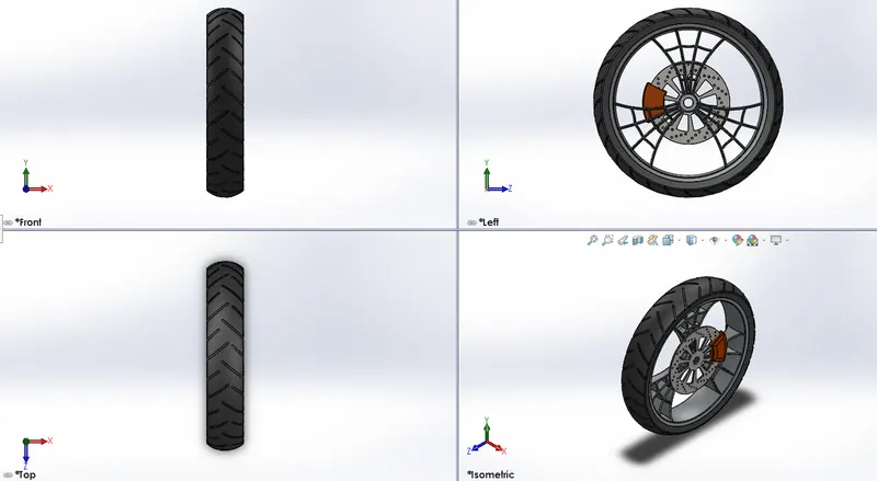
Figure: 4.7.1 Overall views of Front Wheel
8-REAR WHEEL :
A Wheel is a circular block of a hard and material. its help in the motion of the vehicle and it recevies power from the engine through chain drive.
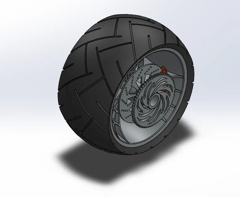
Figure: 4.8.1 Rear Wheel
FEATURES USED :
- Revolve Boss/Base
- Extruded Boss/Base
- Extruded cut
- Revolve cut
- Circular Pattern
- Trim
- Fillet Entities
- Combine
- Chamfer
Procedure to Create a model of Rear wheel :
- Open the Solidworks. Then, click on the new to start modeling.
FOR RIM :
- 2D sketch is created on front plane by given dimensions, relations is fully define a sketch. While Sketching we used the three point arc, spline and line commands.
- The revolved extruded using an imaginary axis at the origin. A spider wed design of the rim is created on the front plane and extruded using mid plane extrude feature.
- Add the spider web is circular patterned to requred numbers and combine the spokes and rim by using combine features to form a single body.
- Chromium plate appearance is applied.
FOR ROTOR :
- Create a circle sketch on the front and extrude it to the required dimension.
- Create the necessary holes using circular pattern.
- Chromium plate appearance is applied
FOR CALIPER :
- A sketch is created by using circle and lines and remove the unwanted skecth by using trim command.
- Extrude the 2D sketch of mid plane extrude the caliper profile.
- Create a chamfer on front and back face of the caliper and make a fillet of sharp edges.
- Siena (car Painted) appearance is applied
FOR TIRE :
- A 2D sketch is created converting entities of the rim on front plane. While sketching line and three point commands.
- Create a revolve the selecting the sketch by using the Revolve Boss/Base feature.
- Create a profiles on the outer surface of tire for grip.
- Matte rubber appearance is applied.
FOR SPROCKET :
- Sketch a circle and Extrude it to arequired thickness.
- Create the chamfer to the outer edges and create a tooth profile on the apply extrude cut. Add fillet to the tooth profile edges.
- Create the sprocket using the circular pattern feature and required number of teeth.
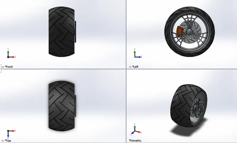
Figure: 4.8.2 Overall views of Rear Wheel
9-OIL TANK :
Oil tank is used to storing lube oil to lubricate the engine parts and which ensures it's smooth running.
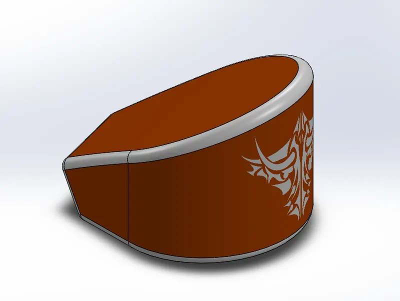
Figure: 4.9.1 Oil Tank
FEATURES USED :
- Extruded Boss/Base
- Combine
- Shell
- Fillet
Procedure to create a model of oil tank :
- Create a 2D sketch by selecting top plane and extrude the sketch by using Extruded Boss/Base command. while creating sketch Three point arc and line commands are used and the sketch is fully define relation.
- Create a another 2D sketch by selecting the front plane and extrude the sketch by using Extruded Boss/Base command. While creating sketch spline and line commands are used and the sketch is fully define relation.
- Now split the bodies and remove the unwanted part to obtain the oil tank. Add fillet to oil tank.
- Create a hellow of required thickness by using shell feature.
- Add siena appearance to the oil tank.
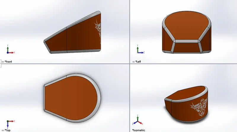
Figure: 4.9.2 Overall views of Oiltank
10-CHASSIS :
To support the load of the body, engine, gas tank, front fork etc.
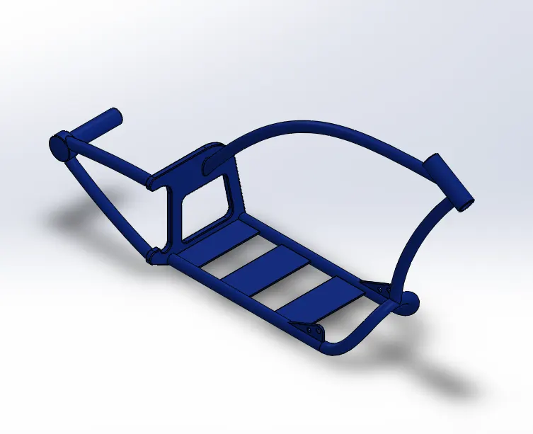
Figure: 4.10.1 Chassis
FEATURES USED :
- Extruded Boss/Base
- Revolve Boss/Base
- Linear Pattern
- Extruded cut
- Revolve cut
- Project curves
- Swept Boss/Base
- Dome
- Combine
- Mirror
- Chamfer
- Fillet
Procedure to create a model of Chassis :
- The blueprint of the chopper is imported to the part design on front plane, by adjusting the location, transparency and the sketch of the chassis is carried on this blueprint.
- Create a 2D sketch on front plane with 4mm thickness tubes bent and joined using splines and created/projected curves.
- At the end all tubes are connected to a plate and further this chassis is extended till the rear wheel hub.
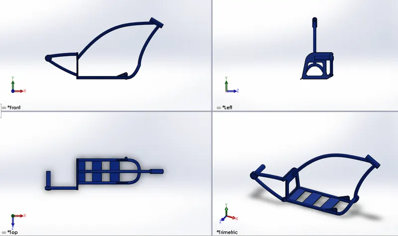
Figure: 4.10.2 Overall Views of Chassis
11-ENGINE :
Engine is the main part/component of the vehicle where the power is generated by ignites the fuel and transmitted to the rear wheel to create the motion of vehicle.
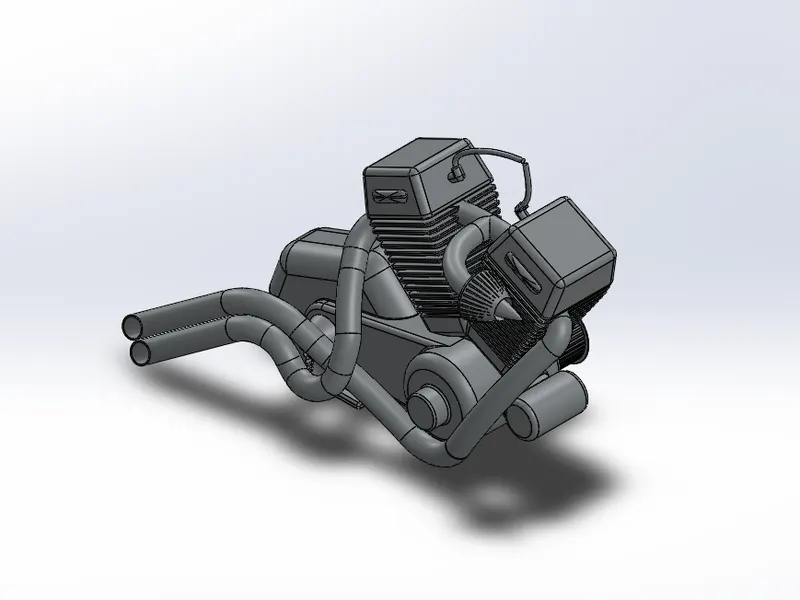
Figure: 4.11.1 Engine
FEATURES USED :
- Extruded Boss/Base
- Revolve Boss/Base
- Extruded Cut
- Revolve Cut
- Circular pattern
- Project curves
- Swept Boss/Bass
- Dome
- Combine
- Mirror
- Chamfer
- Fillet
Procedure to create a model of Engine :
- The blueprint of the chopper is imported to the part design on the front plane, by adjusting the location, transparency and the sketch of the engine is carried on this blueprint.
- Create a 2D sketch on the by selecting front plane and the base of engine is created using three point circle and line and extruded the sketch required dimension.
- Again create a two circles sketch on the front plane and extruded by using Extruded Boss/Base command.
- Create a reference line of to create sketch of engine cylinder part. Create the new plane by selecting the engine cylinder reference line and create the sketch and extruded.
- Mirror the model by selecting the cylinder body by using mirror command and tiwn engine in V-shape.
- Create the sketch for pulley and create pulley using revolve extrusion.
- Using the curves created and projected curves, create the profile of the exhaust pipes and create the swept boss feature. Then spark plugs are created at the end.
- Apply the appropriate material to the engine.
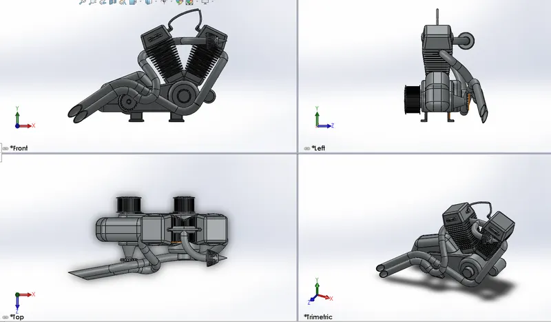
Figure: 4.11.2 Overall Views of Engine
12-FRONT FORK
The front fork is used to guide the entire chopper. Its supports the breaking system, front fender and front wheel.
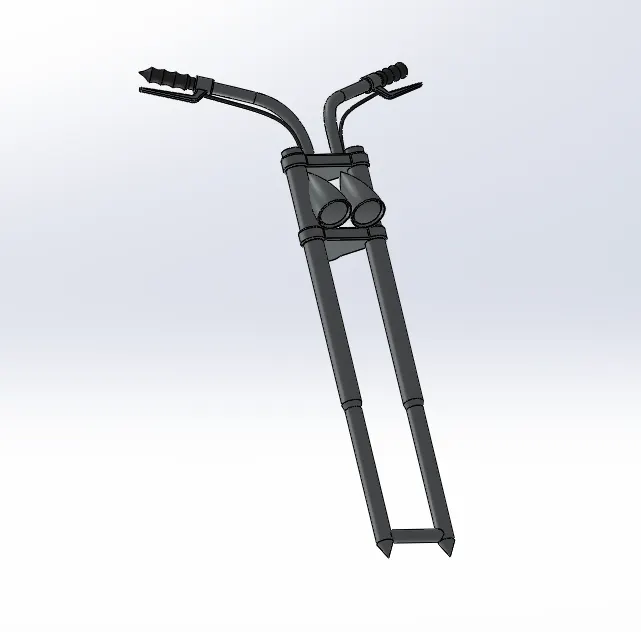
Figure: 4.12.1 Front Fork
FEATURES USED :
- Extruded Boss/bass
- Revolve Boss/Bass
- Extruded cut
- Revolve cut
- Project Curves
- Swept Boss/Base
- Dome
- Combine
- Mirror
- Chamfer
- Fillet
Procedure to create a model of front fork :
- Create a long tube on the front plane by creating the sketches with dimensions and revolve extrude it.
- Create the half of the triple clamp using appropriate dimension sketch.
- Create headlight sketch on the same plane and revolve it.
- On the top plane and draw sketch for Creating the handle using spline and sweep patterns.
- Select all bodies and mirror them along the front plane and combine the entire object.
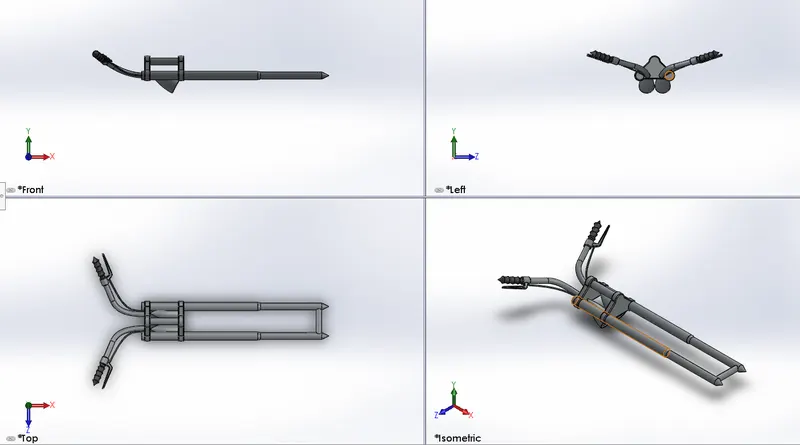
Figure: 4.12.2 Overall Views of Front Fork
13-GAS TANK :
Gas tank is one of the component of the chopper and its used to store and supplies the required fuel to the engine.
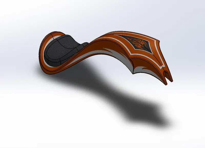
Figure: 4.13.1 Gastank
FEATURES USED :
- Swept Surface
- Loft Surface
- Boundary Surface
- Project Curves
- Knit Surfaces
- Sweep Cut
- Combine
- Shell
- Mirror
- Fillet
Procedure to create a model of gas tank :
- Create a 2D sketch on the front plane by using splines, construction line and projected curve create a surface sweep to create half of the tank.
- Mirror the create part of the tank.
- Create another surface extrude to create the seat and kint the entire surface together and create a sketch on plane and remove the unwanted part by using the revolve cut.
- Apply siena appearance to the gas tank.
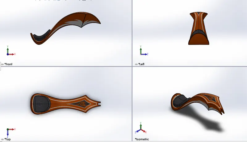
Figure: 4.13.2 Overall views of Gastank
5) ASSEMBLY OF THE AMERICAN CHOPPER
All the designed componentd are taken into the assembly section in solidworks and using different mating features such as concentric, coincident, parallel, etc., the entire assembly of the american chopper is created. Initially, the chassis part is inserted in the assembly by using insert parts in the option. After that the part is inserted in the assembly.
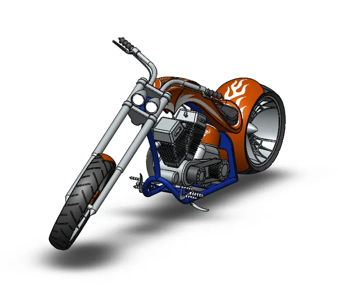
Figure: 5.1 Assembly of American Chopper
Features used to assemble the chopper :
- Mates
- Insert Part
Mates :
Mates create geometric relationships between assembly components. As we add mates, we define the allowable direction of linear or ratational motion of the components. We can move a component within its degrees of freedom, visualizing the assembly's behaviour.
Insert Parts :
We can insert the other components which need to be mated with the prime fixed component.
6) RENDERING :
Once the application of the decals is finished, the assembly chopper is taken into Photo-View 360 and Solidworks Visualize. Here various aspects such as camera, external lightning, background scenes, etc. are taken into consideration before the creation of the final rendering. The final rendered images of the American Chopper are derived
- Render on Photo-View 360 :
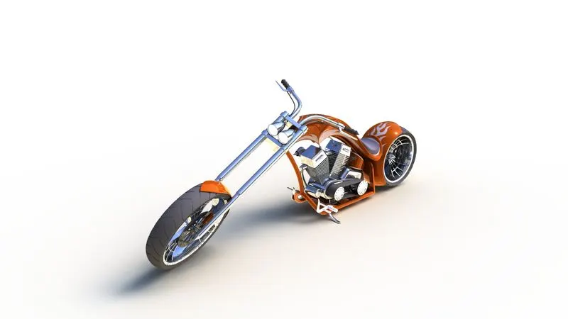
Figure: 6.1 0 Camera-1 View Of Chopper
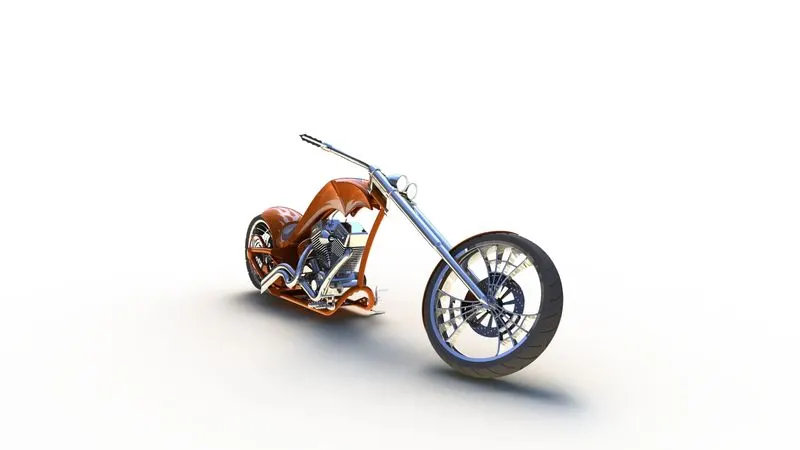
Figure: 6.2 camera-2 View of Chopper
- Render on SolidWorks visualize :
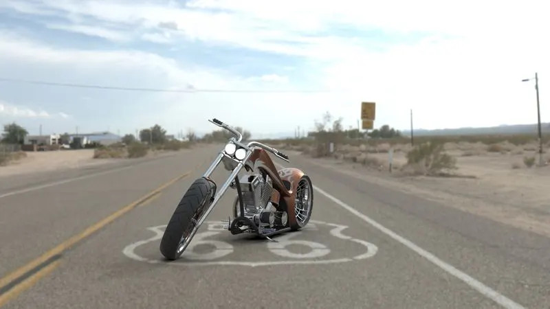
Figure: 6.3 Camera-1 view of chopper on Route 66
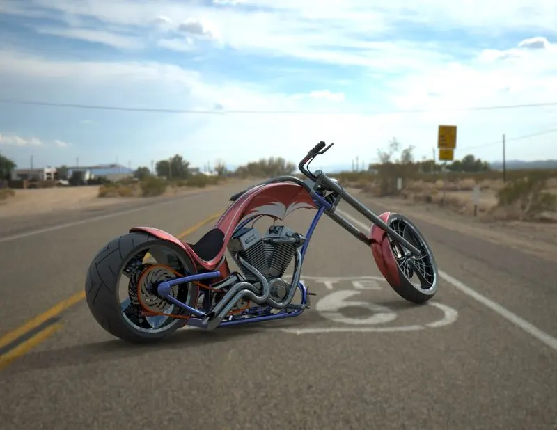
Figure: 6.4 Camera-2 view of copper on Route 66
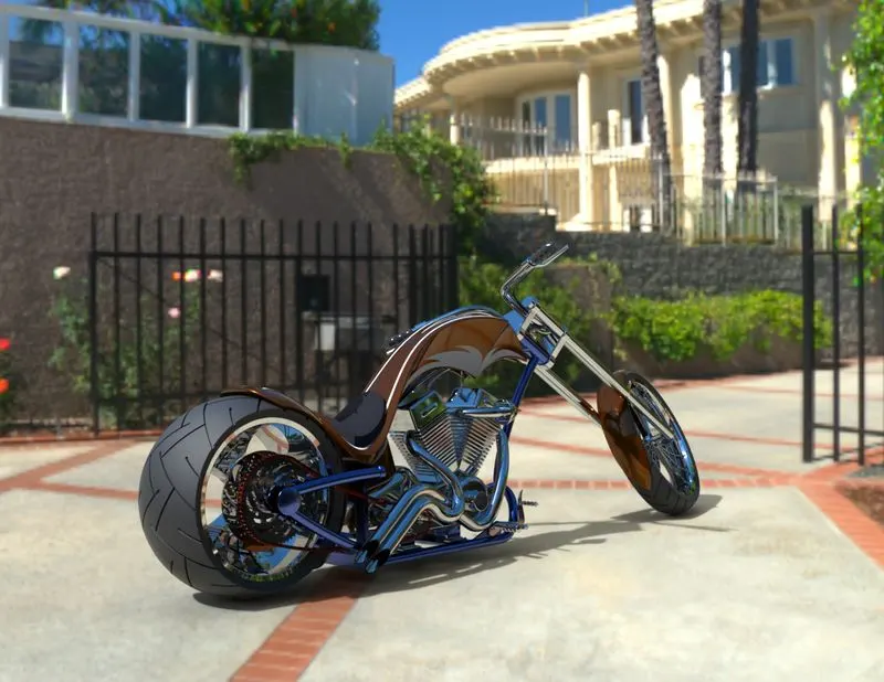
Figure: 6.5 Camera-3 View on Sunny Driveway on Chopper
7) CONCLUSION :
- The parts of the chopper are sketched and modelled in the Soildworks.
- The parts are inserted into the assembly environment and by applying the mates chopper is assembled.
- The realistic image was rendered with the use of the Photo-View 360 & Solidworks Visualize.