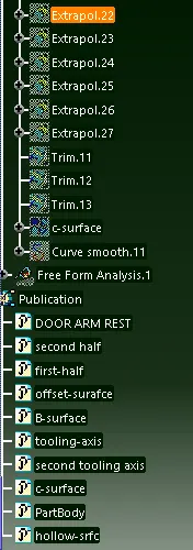
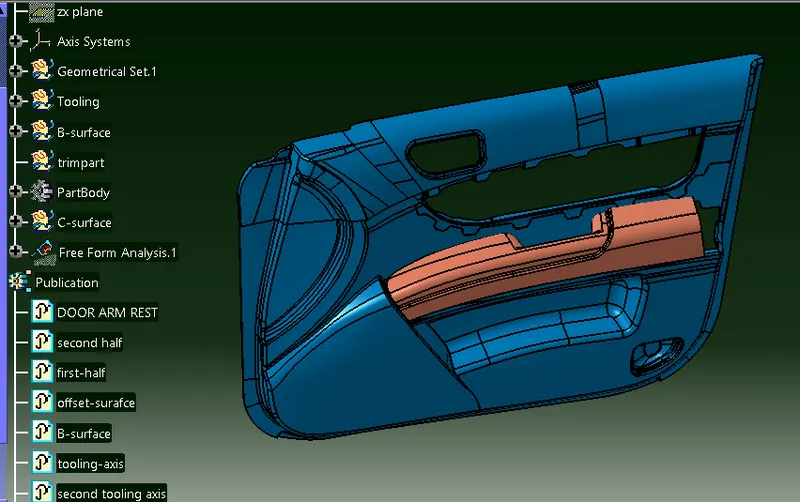
Door Arm Rest Week 8 Challenge
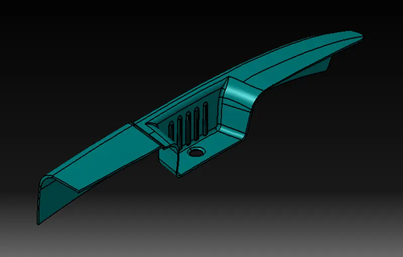
Door Arm Rest
OBJECTIVE: The main objective of this project is to find the tooling axis and draft analysis and create the B and C surface give thickness 2.5 mm.
DRAFT: The draft is something that allows the component to release or eject from the mold properly. The draft is required on all parts in the direction of mold movement in order to allow parts to release properly. Most parts or applications require a minimum of 1/2 to 1 degree, however, 3 degrees is widely accepted as the norm.
The draft is given in the direction of the tooling direction or core cavity opening.
If we don't give the draft to the component it strick to the mold and friction also act so we get the damage in our part so to overcome this we give some draft angle to overcome this problem.
Step to do Analysis
- first, we upload the screen data which we get from the styling surface this surface is called A-Surface.
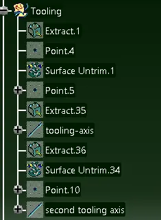
- We take the point in the A-surface and take the axis and intersect the surface and axis with the help of the intersection command.
- Then we use the line command and row two line in our model where we have a given angle surface and use another line command used as bisecting and select both lines and we get the new line in the direction where we want to choose our tooling direction.
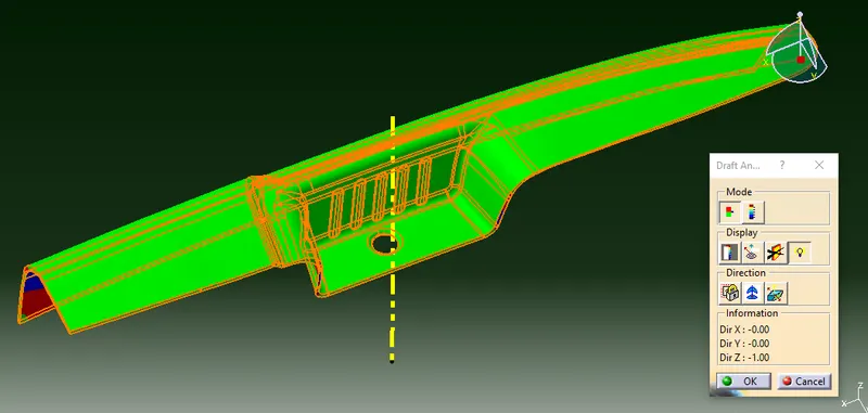
- then we go to insert in insect select analysis and select feature draft analysis and click there and then analyze the model first select the direction and locked and click on the surface and we get the result in color as well as the data value.
Surfaces
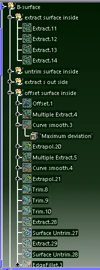
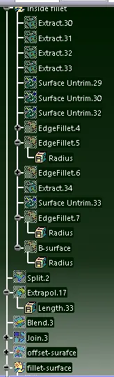
- Surface B: Surface B is like when we give the thickness of the surface this is called surface B.
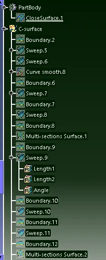
- Surface C: Surface C is the surface that joins the two surfaces this is called surface C.
Commands
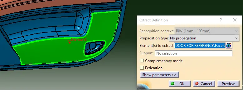
- Extract: This Tool basically used to Extract any surface of the model. First, select the surface using the no propagation option and click ok as shown in the figure.
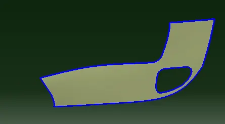
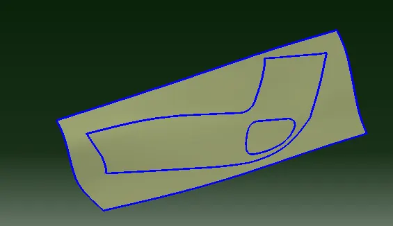
- Untrim: This tool is used to Untrim the Existing surface which before trimmed and we do untrim and surface get expanded accordingly. As shown in the figure.
1) before the untrim 2) After the untrim.
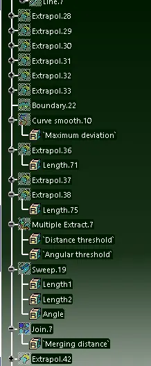
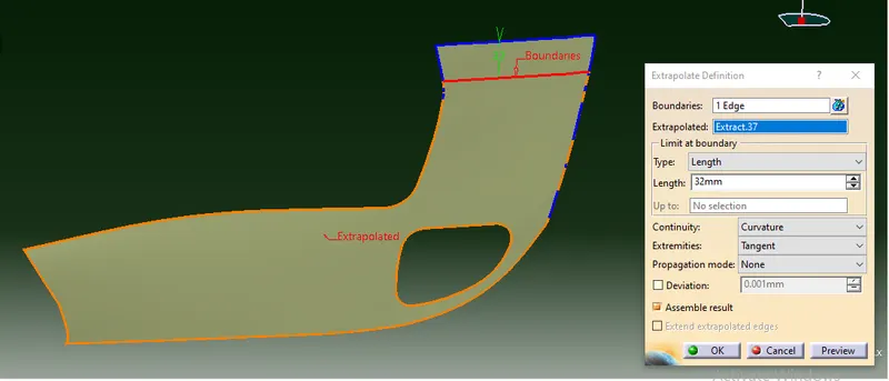
- Extrapolate: This is used to give extra material in an existing direction
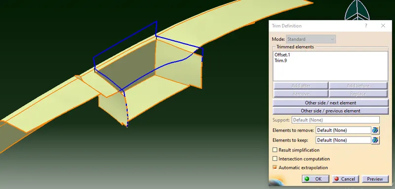
- Trim: this is a very important tool it is used to trim and joint two surfaces together and remove extra material from the model. as shown in the figure.
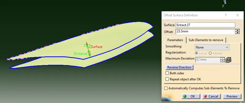
- Offset: This command is used to Offset the existing surface as shown in the figure.
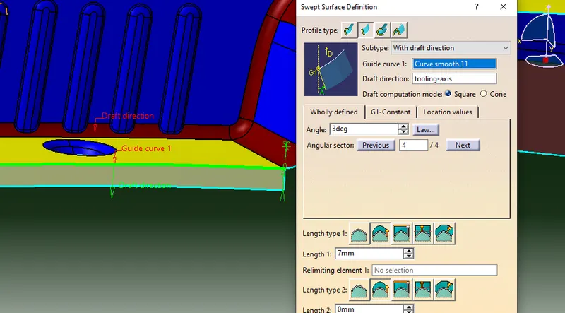
- Sweep: we used here two types of sweep command
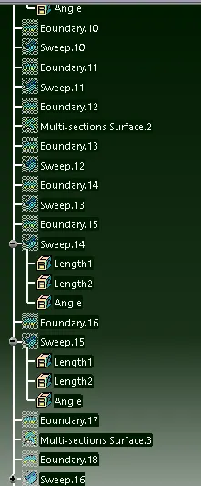
1. Line: In this, we used draft direction in this sweep command we add the material in the tooling direction and also take a draft angle as shown in the figure.
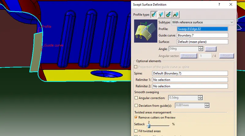
2. Explicit: In this, we used the reference surface we can use the surface as the reference here as shown in the figure.
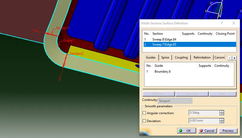
- Multi-Section Surface: This is used to connect the two surface shown in figure.
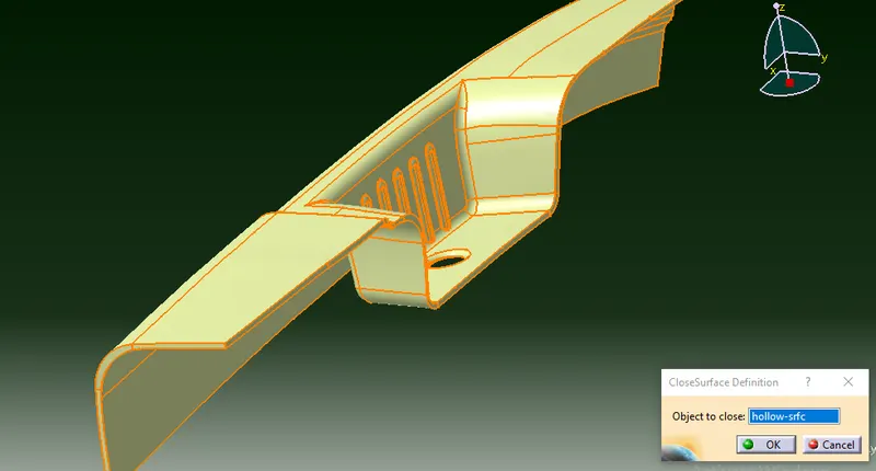
- Close Surface: this command is used to close the surface as shown in figure>
Tooling axis: The purpose of the tooling axis is to tell about the product can be able to manufacture or not if it lies under the tooling angle criteria it will be going to manufacture otherwise it will not release easily from the molding. basically, tooling angles give easy relief. green area represents it ie under the tooling angle.