Door Arm Rest Week 8 Challenge
DOOR ARM REST
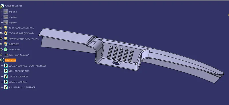
Tree structure
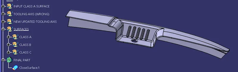
Surfaces and Closed surface
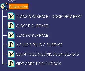
Publications
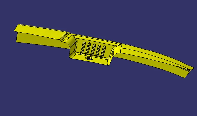
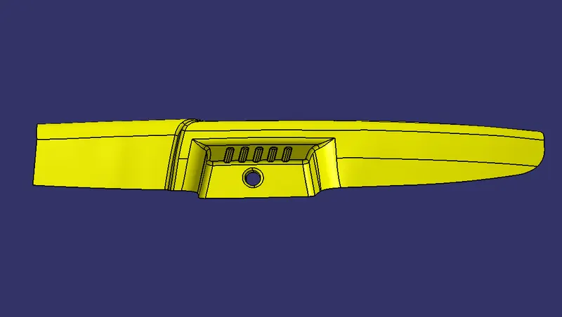
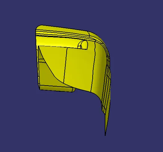
Class A surfaces in Isometric, Top and side views
After analysing the Class A surface from different views, the draft analysis was done along a line normal to the highlighted face in the picture.
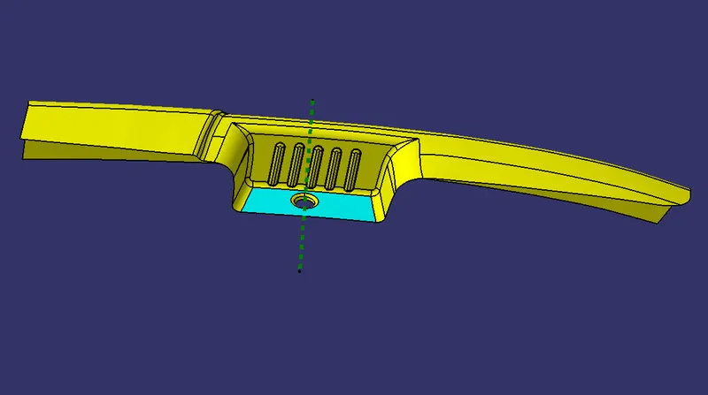
It was clear that the ribs and one of the faces mentioned will not get clear under the tooling along Z-axis.
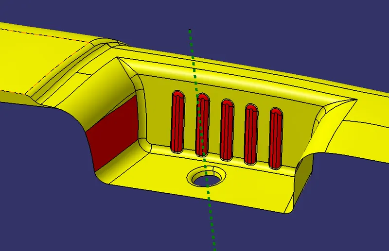
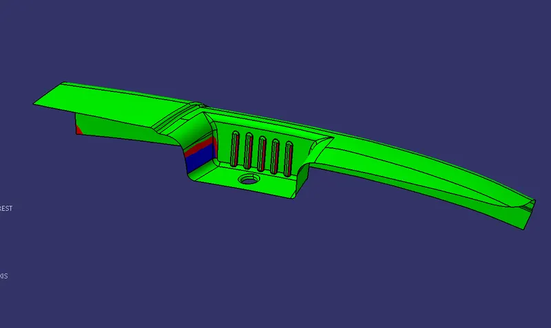
Draft analysis at 3 degree.
So in such cases, the use of side core comes into play.
For adding the rib and clearing the side wall face, we need to create an axis which will be normal to the highlighted face as given below-
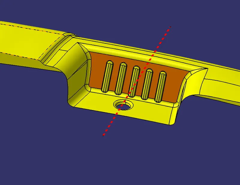
Side core tooling axis and face normal to it.
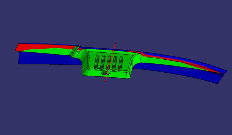
Draft analysis done at 3 degree draft angle and along the side core axis. As per the draft analysis, the ribs feature and the side wall face was clearing in the tooling side core axis.
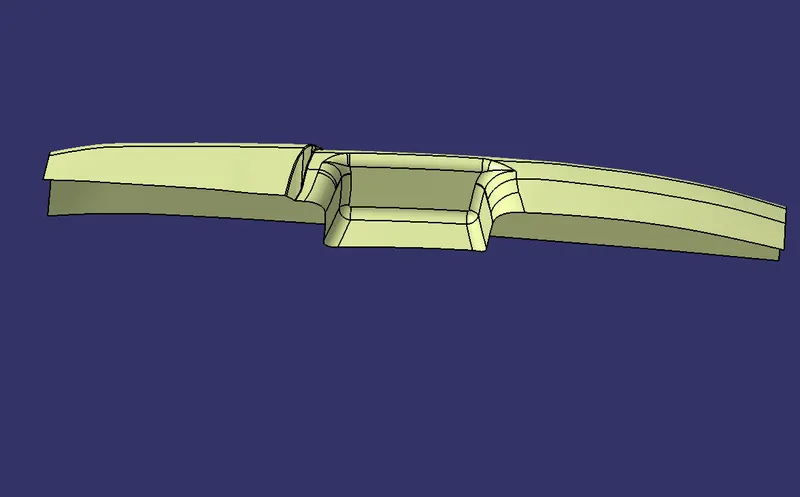
Then the Class B surface creation was done.
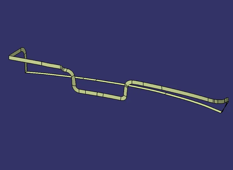
Then class C surface was created using various operations like sweep, multi-sections, and extrudes.
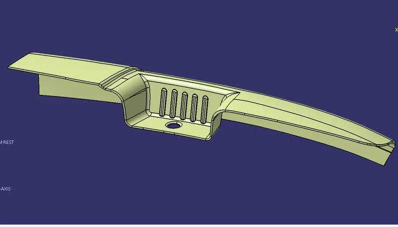
Final trim surfaces
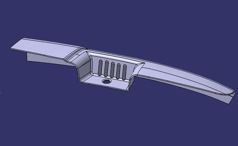
Final solid part made by using closed surface feature
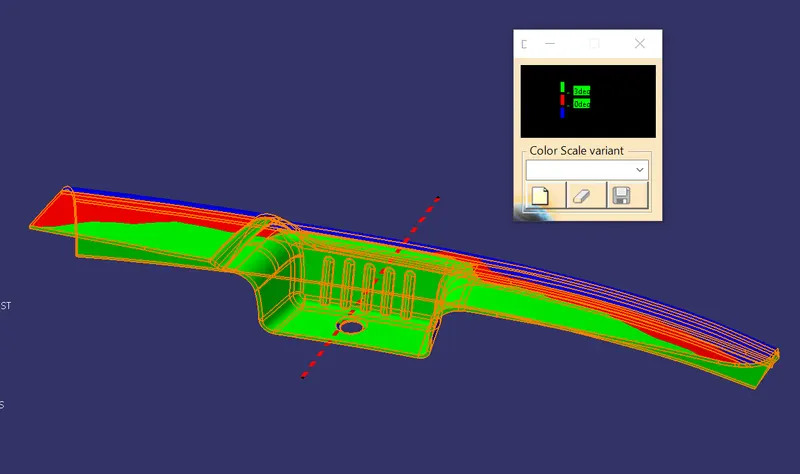
Draft analysis done at 3 degree draft angle through the side core axis
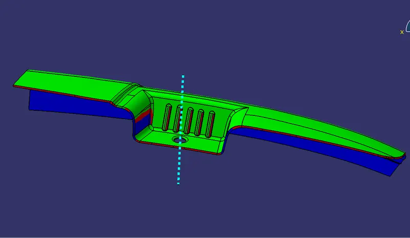
Draft analysis done at 3 degree draft angle along Z-Axis. Here the C surfaces are in red contours (3 to 0 degrees). So trying at 4 degree draft angle.
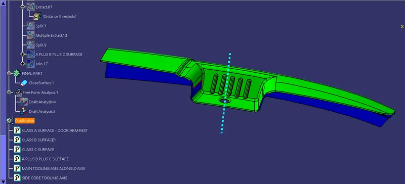
Draft analysis at 1 degree draft angle. Still some faces of Class C surface were showing blue contours (angle less than zero degrees), but those were getting cleared in side core Tooling axis.
Hence this component is manufactureable under injection moulding process under the Tooling axis along Z-Axis and also with the help of side core and its corresponding tooling axis.