Week 8 - Challenge 3 - Switch Bezel Design
SWITCH BEZEL DESIGN
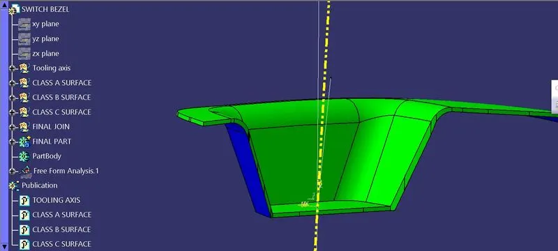
Tree structure
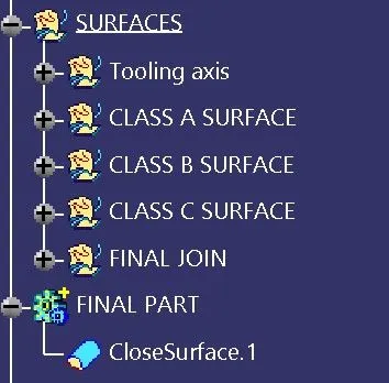
Surface set
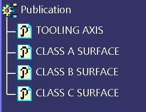
Publications
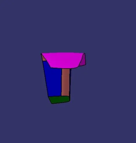
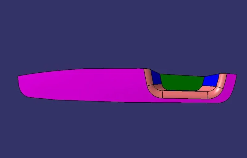
Front view, side view and top view of Class A surface. After understanding the Class A under different views, it was clear that the tooling axis should come normal to the top view while also taking into account the faces front view direction.
A line normal towards the top view was created as a reference axis. An intersection was created along the front face to get the surface profile. With the help of two lines on the profile we created a bisecting line.
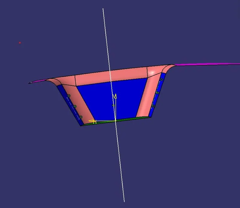
After that, we will create an intersection along the front face to get the surface profile and using them we will make an angled line as another reference tooling axis.
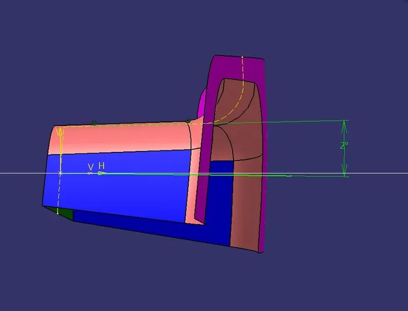
After that, from the two reference axis which we have created, we will create a common bisecting line which will be our main tooling axis.
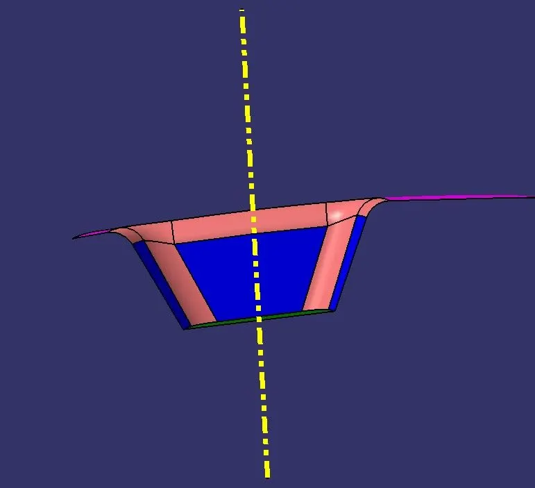
Using this axis, a draft analysis was performed for the Class A surface with a draft angle of 3 degree. It was found that all faces were clearing the draft angle of tooling axis.
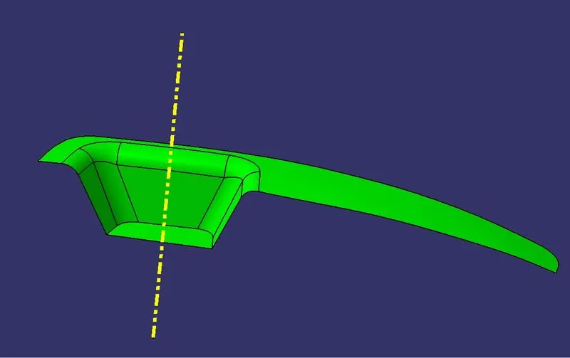
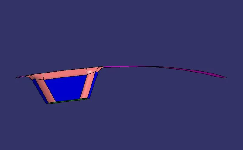
After that Class B surface and Class C surface were desiged.
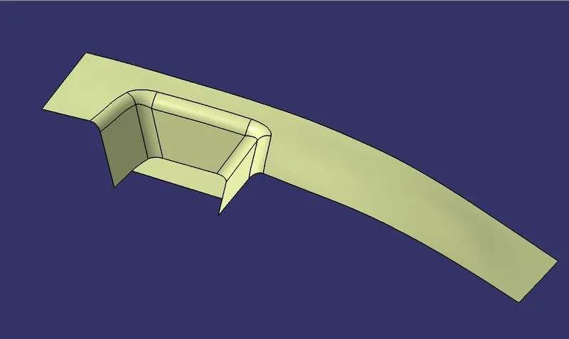
Class B surface
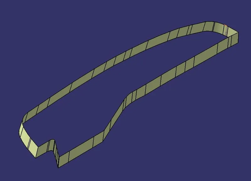
Class A surface
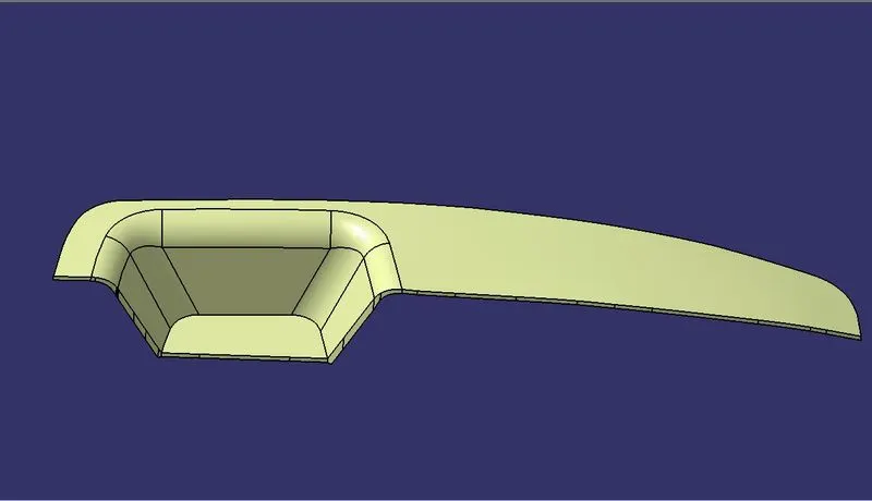
Final surface after trim operations.
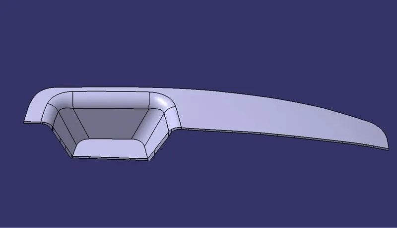
Final solid closed surface after performing closed surface operation.
After forming the part, its draft analysis is done.
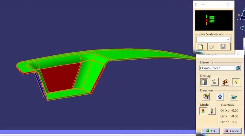
And it was found that the surfaces were not clearing 3 degree draft angle initially applied. So later, the bar was set at lower draft angle of 1 degree and then the surfaces cleared the provided draft angle.
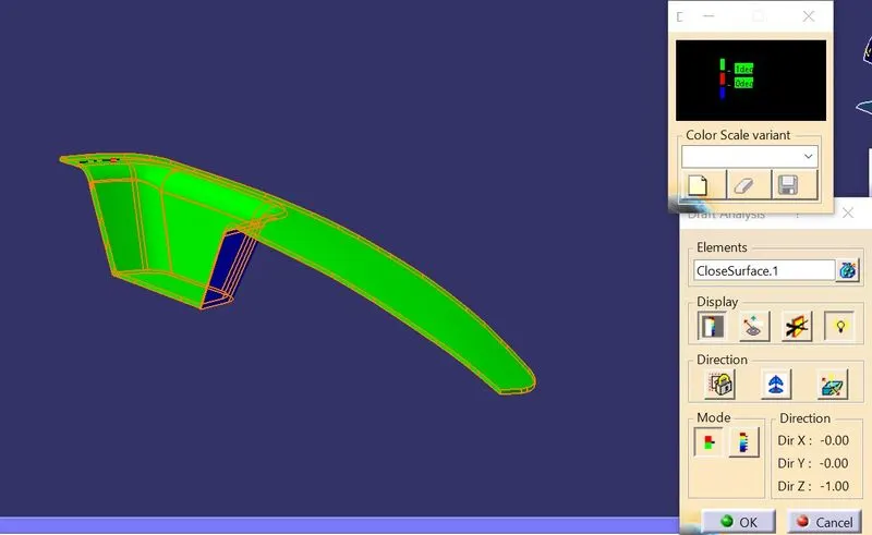
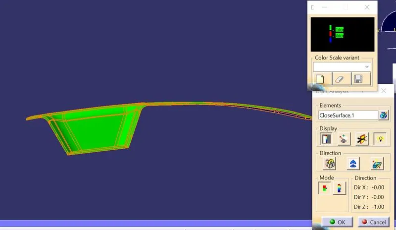
So it was found that the final part can be manufactured with a draft angle of 1 degree.