Week 8 - Challenge 2 - Base Bracket Design
BRACKET DESIGN
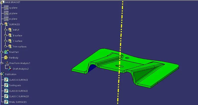
Tree structure
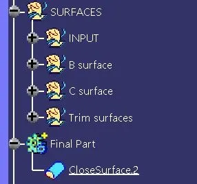
Surface sets
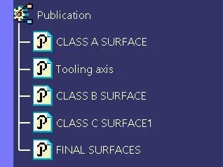
Publications
DRAFT ANALYSIS OF CLASS A SURFACE
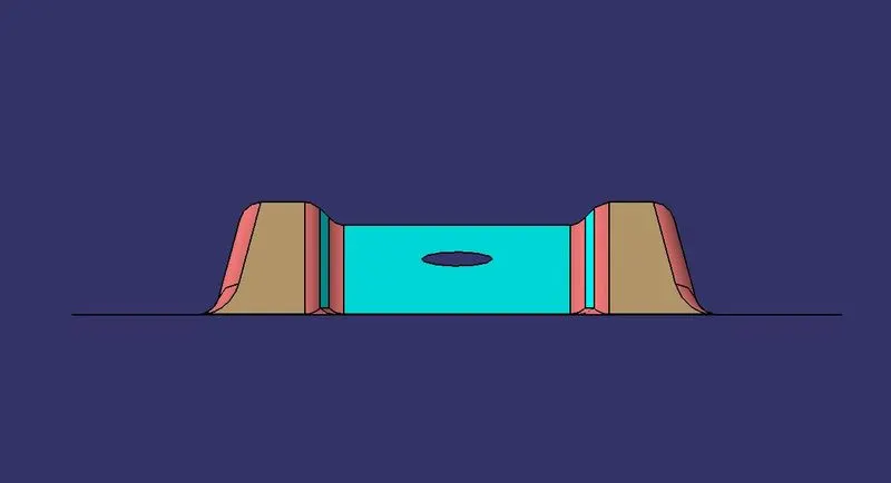

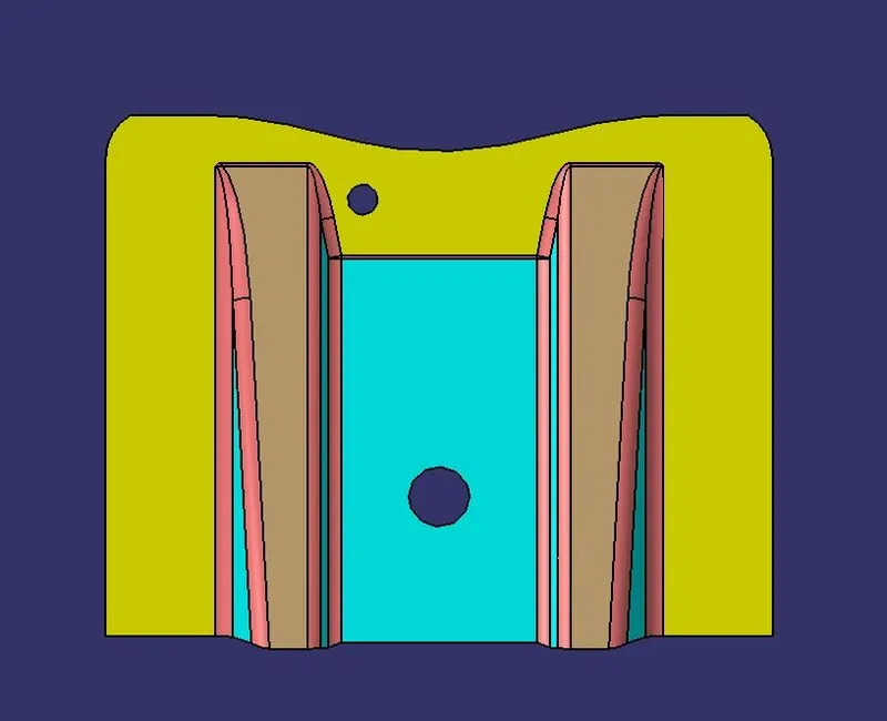
Front view, Side view and Top view of Class A surface
Class A surface was viewed from all angles for identifying the best direction(axis) for tooling. As under front view and side view most of the flat faces were not visible and eventually they will not clear the tooling in their respective view. Therefore under top view, all faces were visible and they will get clear under the tooling in that top view.
So, it was decided that the tooling axis would be normal to the top view.
Creation of tooling axis
Sketch was created under Front view for tooling axis as the front view is in normal direction to the top view.
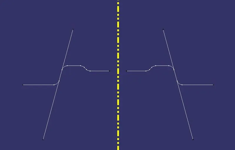
After that an intersection was created using the front plane. Using the profile obtained, two lines along the slant faces were created and from those lines a bisecting line was created.
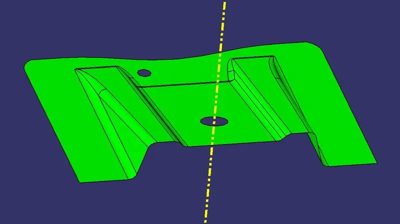
DRAFT ANALYSIS OF CLASS A SURFACE
Now using that line as the main tooling axis, draft analysis was done and all the faces were clearing the 3 degree draft angle.
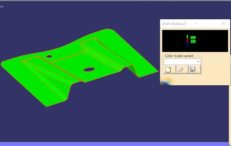
After that Class B surface were created.
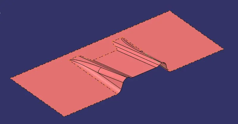
CLASS B SURFACE
And later Class C surface were created.
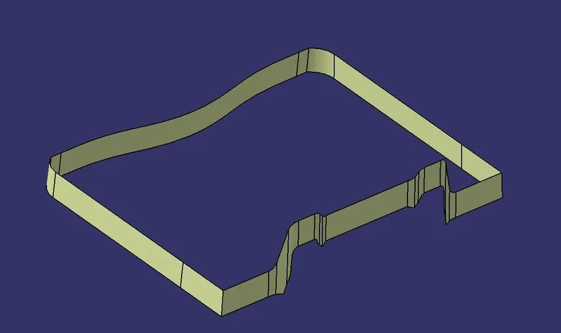
CLASS C SURFACE
Then Class A and Class C surfaces were joined and then trimmed along with Class B surface, to obtain the final surface.
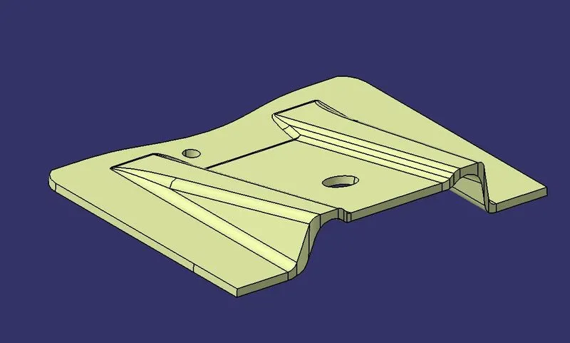
FINAL SURFACES
At last the closed surface feature was used to create solid Bracket part
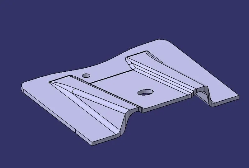
Also, the draft analysis of Final solid part was done and it was found that all the faces were clearing a draft angle of 2.9 degrees.
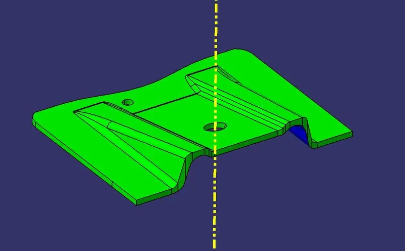
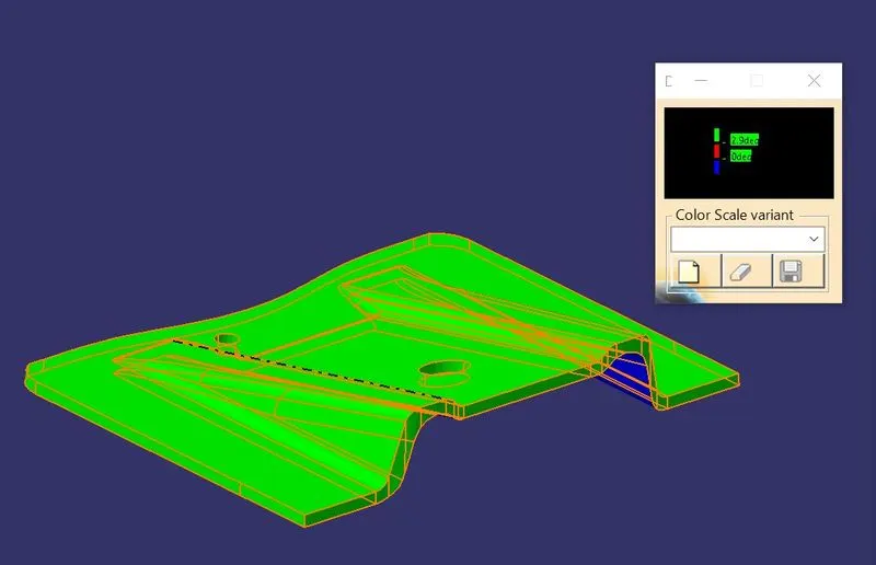
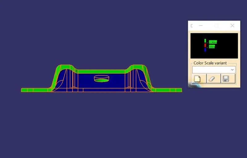
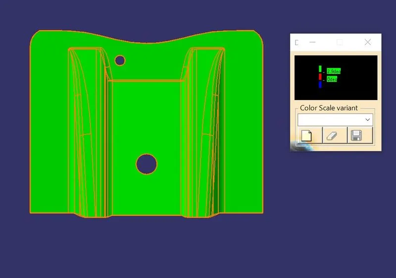
Hence, it was concluded that the part is possible to manufacture under a draft angle of 2.9 degrees.