Week 8 - Challenge 5 - Core & Cavity Design
CORE AND CAVITY DESIGN
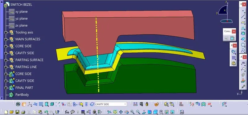
TREE STRUCTURE
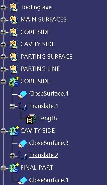
SURFACES AND FINAL CLOSED SURFACES
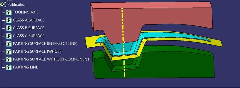
PUBLICATION
DRAFT ANALYSIS
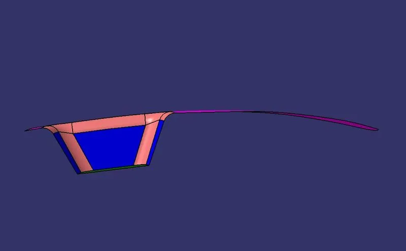
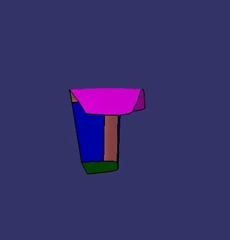
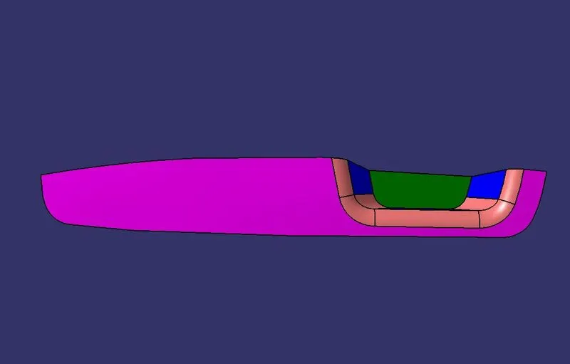
Front view, side view and top view of Class A surface. After understanding the Class A under different views, it was clear that the tooling axis should come normal to the top view while also taking into account the faces front view direction.
A line normal towards the top view was created as a reference axis. An intersection was created along the front face to get the surface profile. With the help of two lines on the profile we created a bisecting line.
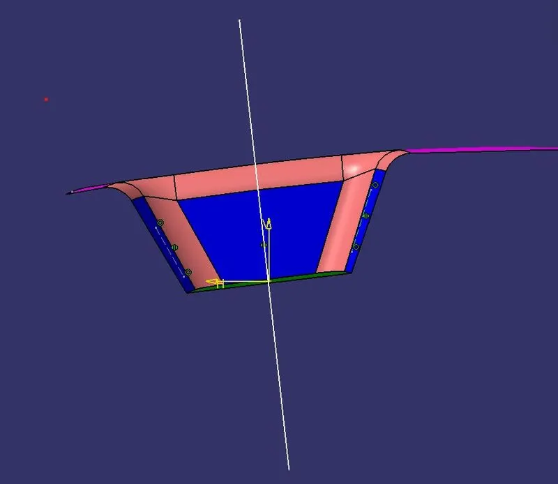
After that, we will create an intersection along the front face to get the surface profile and using them we will make an angled line as another reference tooling axis.
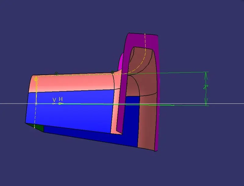
After that, from the two reference axis which we have created, we will create a common bisecting line which will be our main tooling axis.
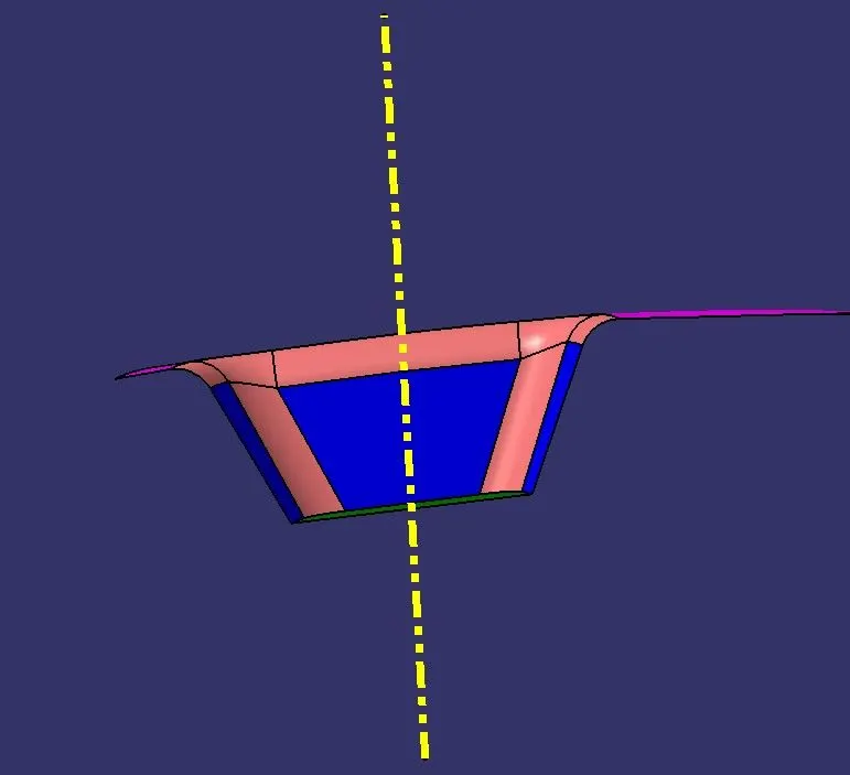
Using this axis, a draft analysis was performed for the Class A surface with a draft angle of 1 degree. It was found that all faces were clearing the draft angle of tooling axis.
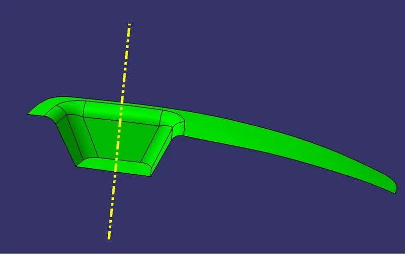
After that Class B surface and Class C surface were desiged.
CORE SIDE
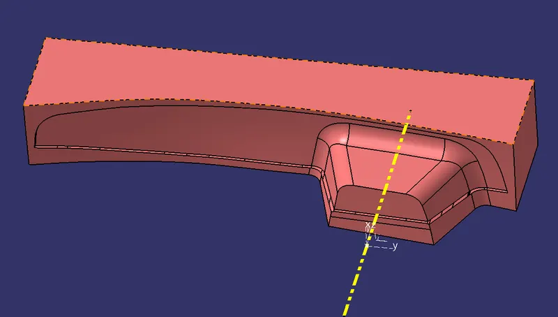
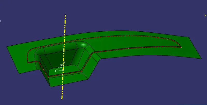
Class A and Class C surface were extracted and joined. Then they were trimmed with Class B surfaces to obtain the parting surface. After then extrapolation was done and then a rectangle enclosure was extruded. Then extrapolated and extruded rectangular were trimmed together. After then the top surface was filled and all surfaces were joined together.
At last, closed solid was created using closed surface feature.
CAVITY SIDE
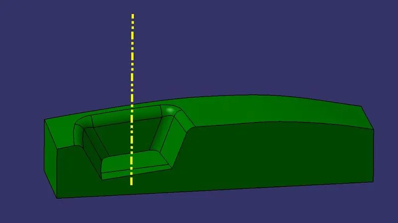
In similar way, Cavity side was also created.
PARTING SURFACE
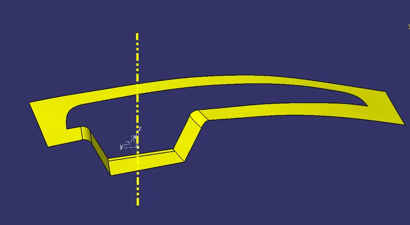
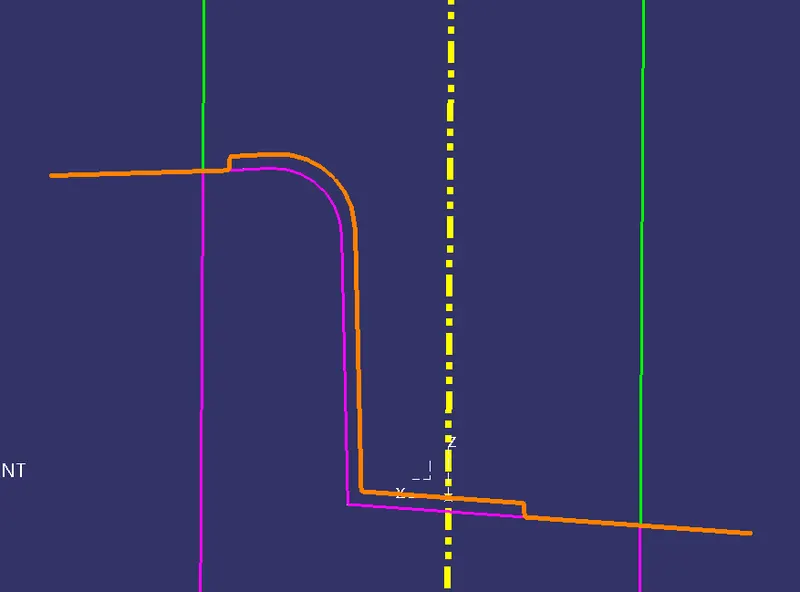
PARTING LINE