Door Arm Rest Week 8 Challenge
DOOR ARM REST
Objective: Creation of Door Arm Rest and making it into a solid part according to OEM Standards
METHODOLOGY :
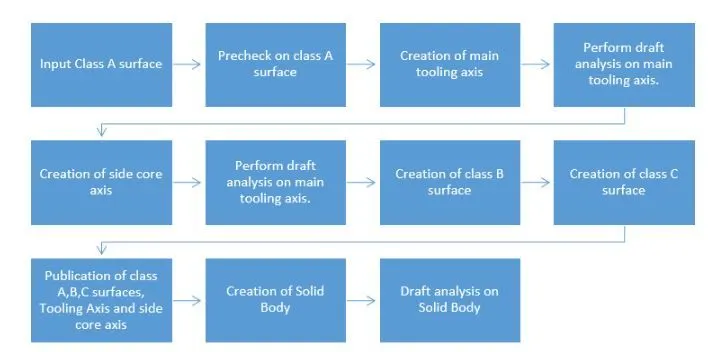
As the given model is having too many complex surfaces it won't get clear with one tooling axis to clear the whole model we need a Side Core/Lifter Tooling Axis
Creation of Main Tooling Axis
- Using Circle/Sphere/Ellipse Center Created a point in the center of Class A
- Then Using Line Command With Point and Direction Created a line Perpendicular to class A and did the draft analysis for class A by moving the compass around the tooling axis create.
Now to clear the remaining part of the Arm Rest, I made a Lifter Axis using the same Procedure point and Direction Direction as the Compass where it can clear the Draft.
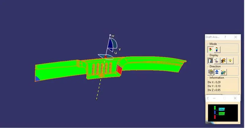
Main Tooling Axis
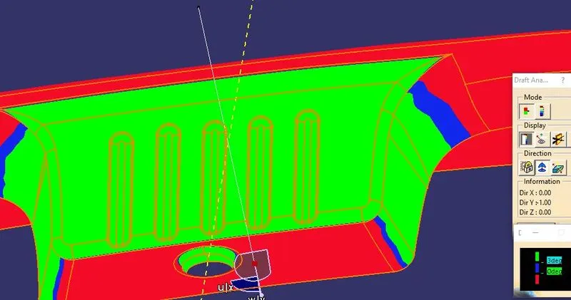
Side Core Tooling Axis
The above picture of both tooling axis shows that in the side core tooling axis also some surfaces had not to get clearing.
After inspecting it thoroughly inform to the styling team which patch they had to rework.
Then after the rework also inspect it when it clears all the surface then move on to the B surface.
Creation of B Surface
There are two methods to create a B Surface
- Untrim and Extrapolate A Surface
- Offsetting the A Surface
For Arm Rest Project I am doing the 2nd method Offset of the required Nominal thickness as the offset value.
By using this method due to the fillet corners some portions are not get offset.
By using a spline command with a multi-section surface it has to solve.
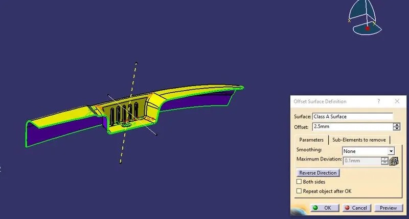
Class B Surface
Class C Creation :
A surface means a visible surface.it will give styler. B surface means the thickness of a part it is not visible it is inside part. c surface means A and B combined to give C surface. Class C surfaces are the backside surfaces that can have tool marks, flashes, and other imperfections without hurting appearance, function.
- To Create the C Surface had to extract the boundaries of A Surface.
- After extract then go to sweep command
- In the sweep command, the option draft direction is there.
- Give the reference curve along with the angle 3 deg outwards towards the outside of the A surface.
- After doing this in the corners some edges are there in the fillet form in the surface use the multisection command to match the sweep
- After sweeping and all the surfaces use the join command to join the C Surface.
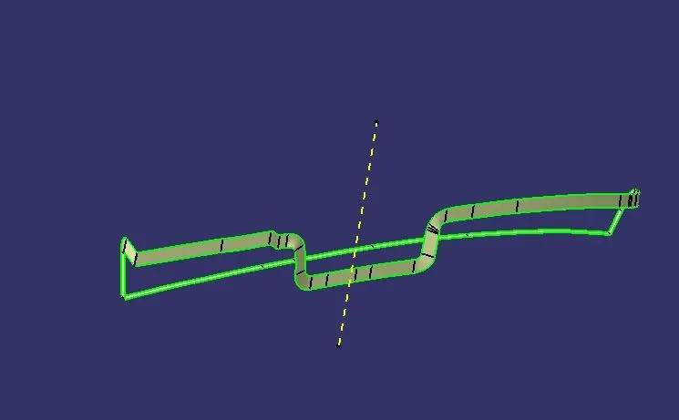
Class C Surface
CLOSED SURFACE
- The next step is to Join the Two surfaces A Surface and the C surface
- After joining the two surfaces Extrapolate the B Surface. In the door armrest, the single-shot won't work perform in a boundary limit.
- After doing this trim the B surface with the join of A and C.
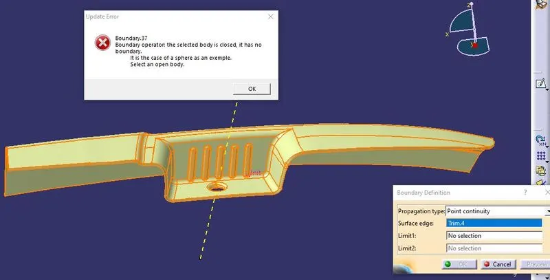
The image shows that there is no boundary in the Armrest Surface.
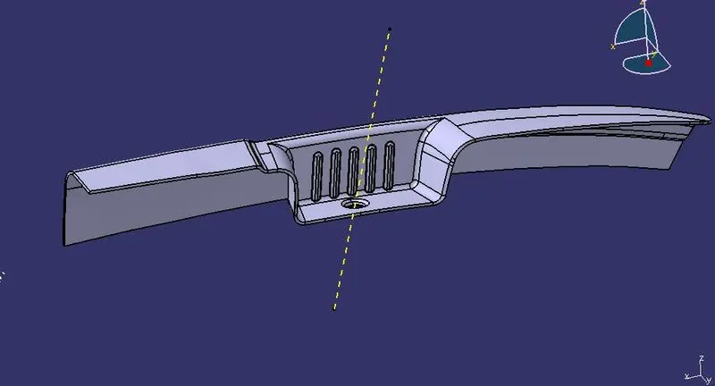
Draft Analysis :
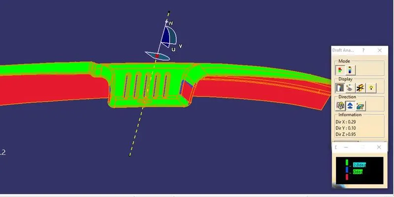
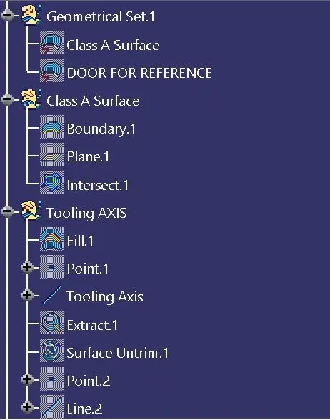
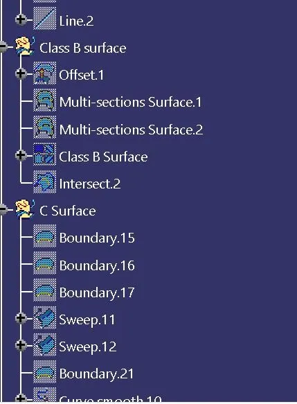
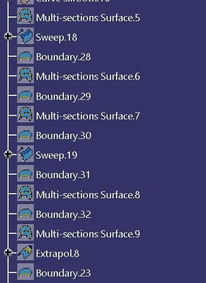
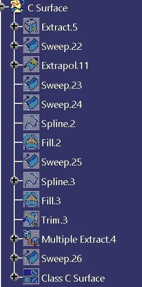
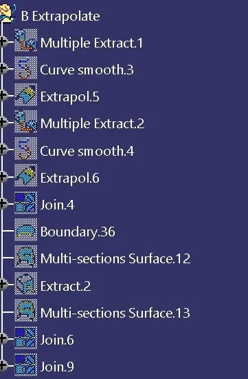
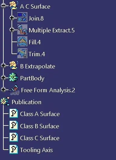
Tree Structure:
Result :
Hereby I can Conclude that the given Armrest is designed according to the OEM standards with the thickness of 2.5 and draft analysis is also cleared using the tooling axes created.