Door Arm Rest Week 8 Challenge
REPORT
AIM
To generate the draft analysis of the arm rest model.
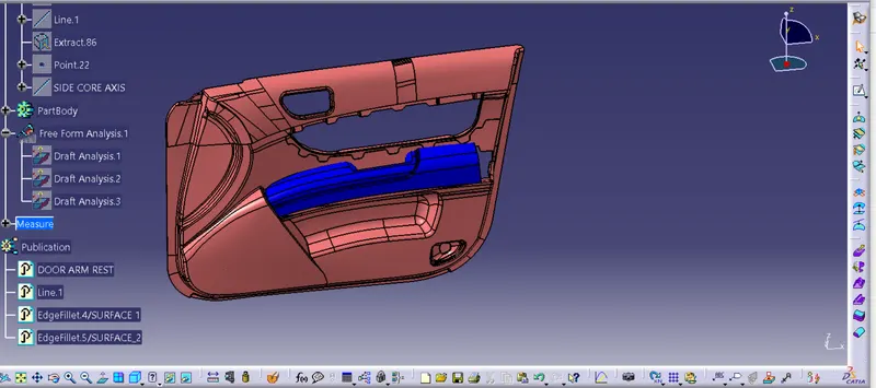
CREATING TOOLING AXIS:
1.Create point on the middle of the hole and insert the system axis.
2.Create intersection on the XY plane. and draw a line on the two walls and create bisecting line using with two lines
3.Create another intersection on the yz plane cut half section abd creating one line on the wall inter section and draw a random line on the point this line gives angle from the inter section line.
4. After creates tooling axis with using above bisecting and random line.
5. Creat anothee tooling direction through y direction.
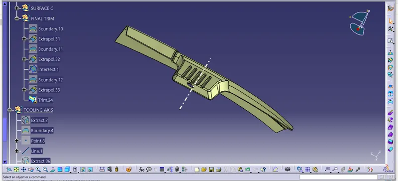
B SURFACE CREATION:
1.Extract the arm rest top surface and untrim and do extropolate up to 60mm.
2. Create a sketch on the middle of the surfaces for getting two curves between the surfaces. create a line through y directiuon. and extrude a surface using guide curve and create a bend between the one of the top surface and middle plane.
3. Trim the all surface of the top and offset 2.5mm.
4. And extrude walls and unitrim it than extrapolate up to 50mm and trim the surfaces.
5. Give the edge fillets based on dimensions of the fillets.
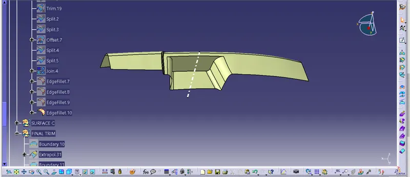
CREATION C SURFACE AND MAKING IN TO SOLID PART:
1. Create a boundaries on class A Surface on step by step based on straight plane and curved planes.
2. creates boundaries differently divided by the angle of the bondary.
3.Create sweeps on bondaries
4. we will get small gap betweeen the surfaces. Its cleared using with joining option gap value is maintain 0.3
5. Trim the surfaces and join the class A and class B surfaces than we will get c surface.
6. Than will go to part design and fill the surface.
7.after that we need to make the solid out of our surface design so for that we have to check the boundaries .
8. we need to make sure the surface design has not opening after that we are going to the option called close surface.
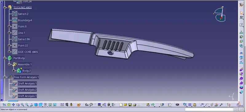
9. First we need to change the page we need switch to the part design after that i am able to change the surface design in to solid state.
10. so by clicking the close surface we can able to get the fullly close object thats mean a solid object we can able to obtain.
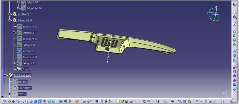
DRAFT ANALYSIS FROM TOOLING AXIS:
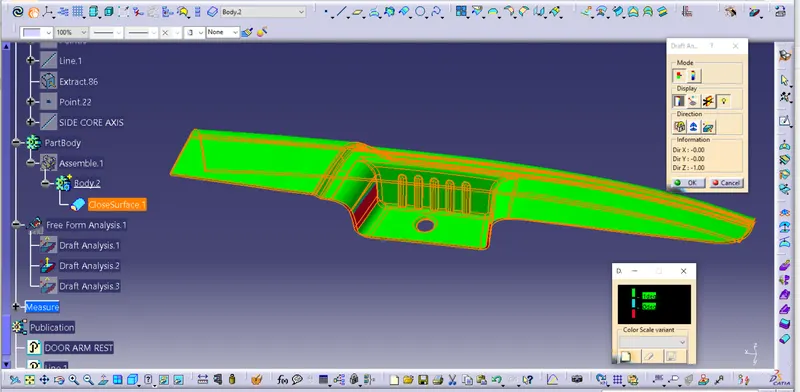
Open the draft analysis by insert> Analysis> feature draft analysis. Select the compass direction in draft analysis and align it to the tooling axis and then lock it.
After locking it a cross symbole will occur at the ponter, select the surface and selected turns in to green.
In draft analysis 2 box, select the green column to change the draft angle to 3 degrees.
The color should be green in colour.
DRAFT ANALYSIS FROM SIDE CORE AXIS:
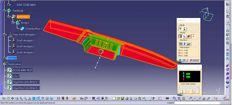
open the draft analysis by insert> analysis> feature draft analysis. Select the compass direction in draft analysius and align it to the side core axis an then lock it.
After locking it a cross symbole woll occur at the point in all over the surface , select the surface and selected turns i to green.
In draft analysis 2 box, select the green column to change the draft angle to 3 degrees.
The color should be green in colour.
CONCLUTION
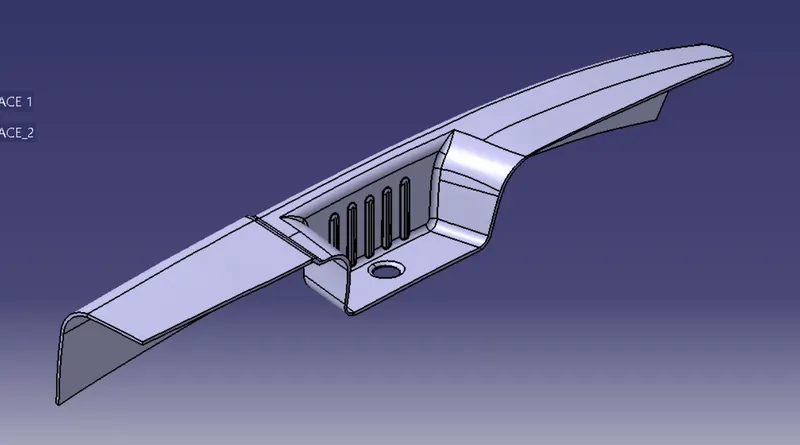
Thus a manufacturing door arm rest console was successfully designed using CATIA V5 surface workbench.
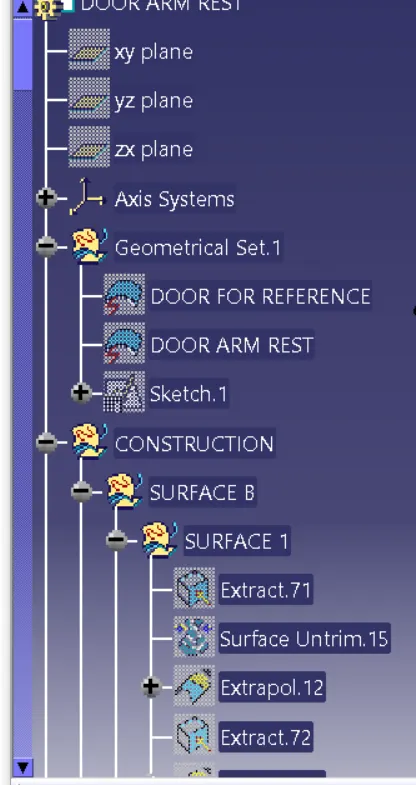
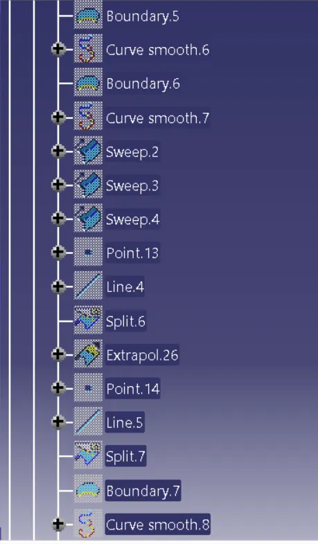
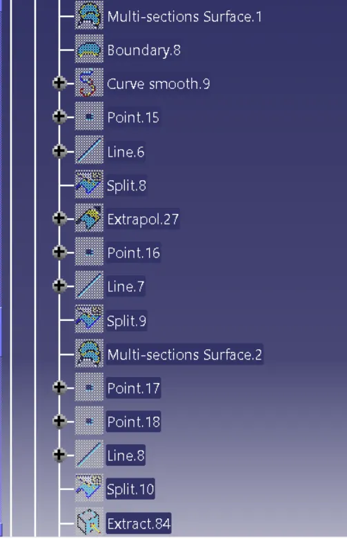
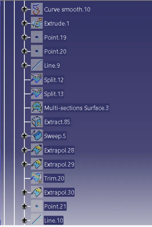
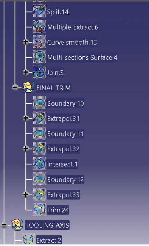
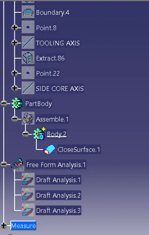
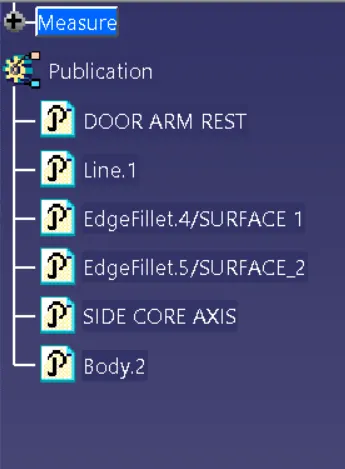
FEATURE TREE:
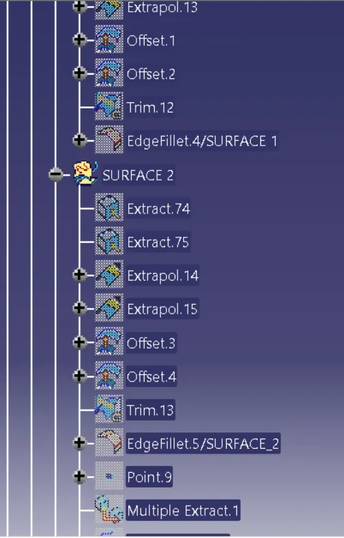
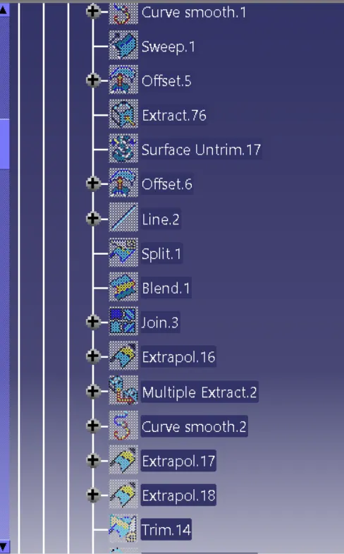
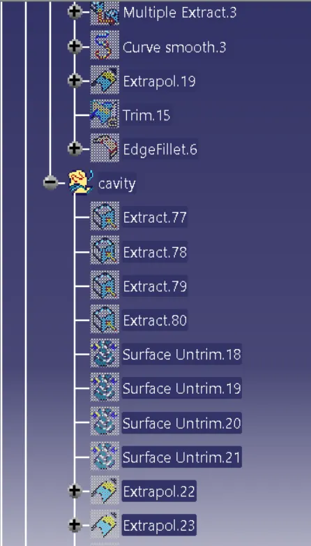
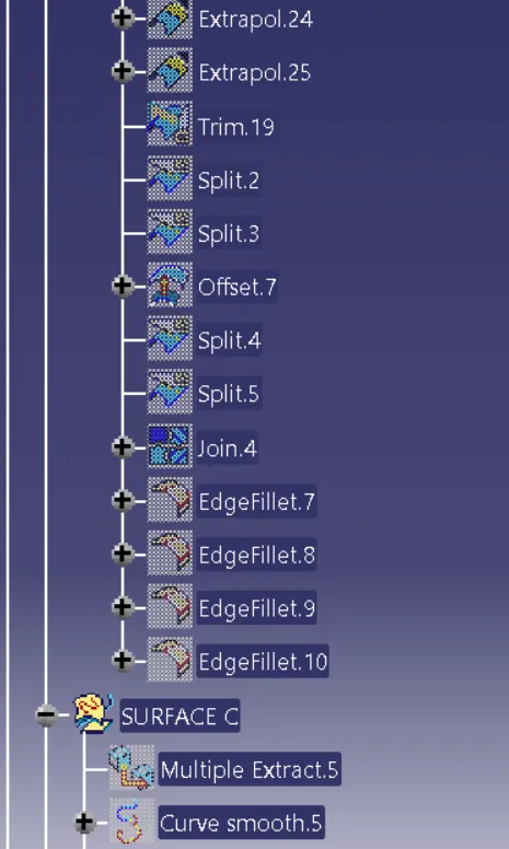
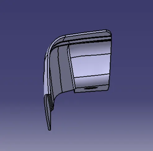
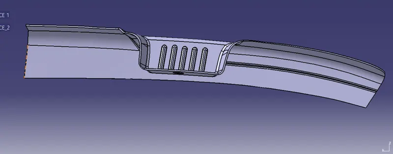
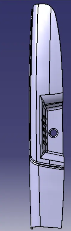
PART MODEL VIEW ORIENTATION: