Week 8 - Challenge 2 - Base Bracket Design
REPORT
OBJECTIVE:
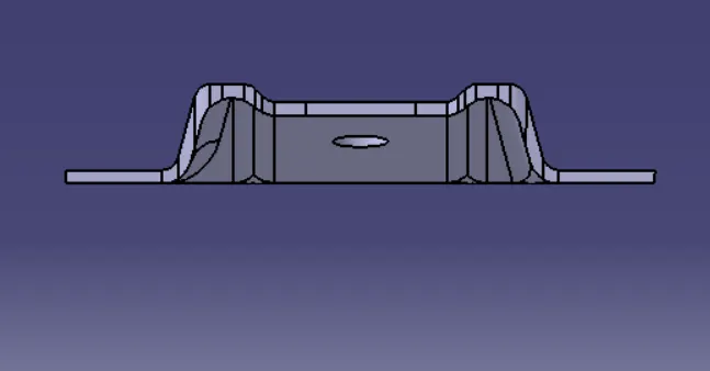
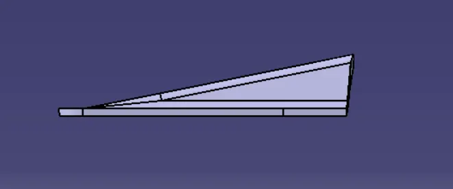
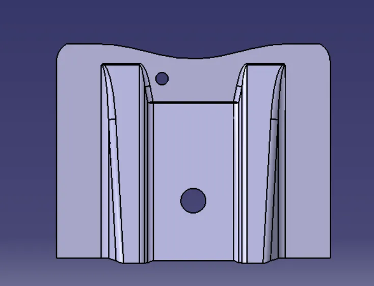
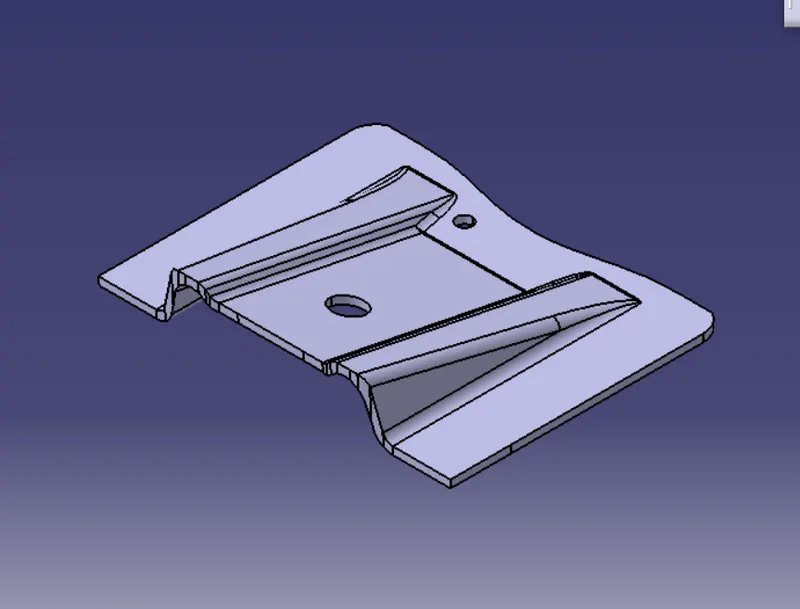
The main of this project is to perform the draft analysis and model the base bracket design through the given class A Surface . Beginning with the creation of the tooling axis, Class B surface. Beginning with the creation of the tooling axis, Class B surface development, and then class C surface and then merging class A,B,C surfaces to form a plastic component. by considering the thickness as 2.5mm
ABSTRACT:
Draft:
1. A draft angle is that applied to each side of most features of an injection molded pert. in otherwords draft is providing tapers on the product features such as walls,ribs,posts and bosses that lie parallel to the direction of the release from the mold part ejection
2. The nominal draft is 3mm for plastic components and for automotive sheet metal components is 7mm
PROCEDURE
connectivity of class A surface:
1. The first and foremost thing to do is to check for the connectivity of the surfaces this is to ensure thst there sre no gaps between the surfaces if gaps are present then it should be resolved.
2. This can be done visually or by creating bondaries, if their gaps are present they are graphically represented by green lines. if not while performing boundary command it shows an error.
creation of dummy axis:
1. This is a nominal line which we construct by analysing the best possible direction(X/Y/Z axis) for the draft for part,this axis is only for reference and is not used for tooling axis.
Creation of tooling Axis for class A surface:
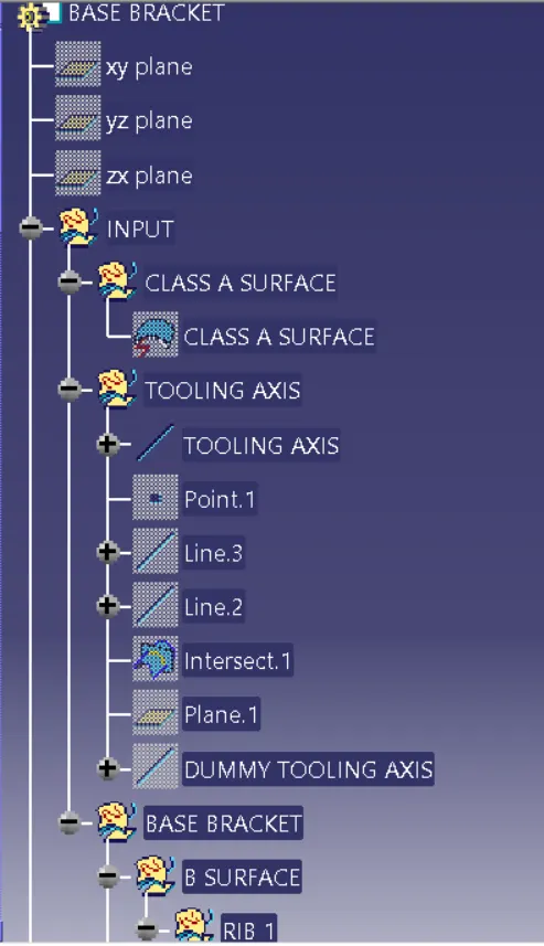
1.Taking the dummy axis as a referance, intersect the class A surface along the different axis (XY/YZ/ZX) Check for the possible places where the part might face difficulties while ejecting the component from the mold.
2. Lines are drawn at the places where the part boundary has difficulties.
3. Later the tooling axis in one direction (lets say X) is obtained by bisecting the lines drawn in the above process
4. In the same way, the other axis is also checked and then the tooling axis in another direction ( lets say y) is drawn
Now both tooling axis are bisected and the final tooling direction is obtained which is further used for all draft analysis axis and later on to developing class C and class B surfaces.
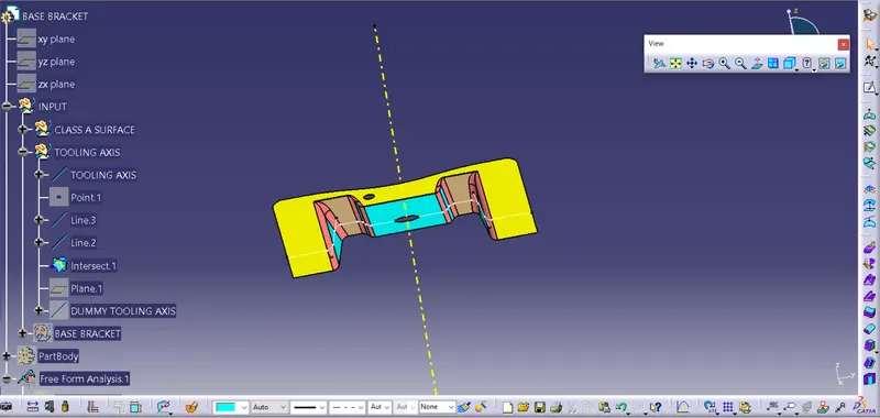
publication:
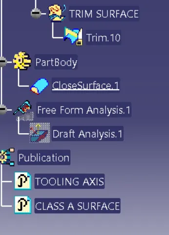
1. The publication is used for easy access to published components. These will come handy while modeling ( We are not required to search the entire tree structure for a particular operation)
DRAFT ANALYSIS:
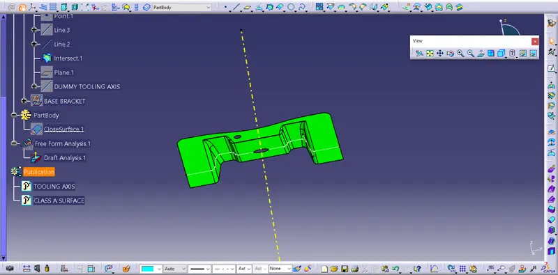
1. Click the insert-analysis-(Feature) Draft analysis icon
2. If material is not on there will be a warning message is shown and then we need to select the material
3. The draft analysis dialog box is displayed ( color scale ), the draft direction, and the direction value.
DEVELOMENT OF CLASS B SURFACE:
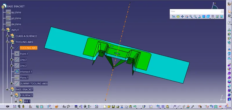
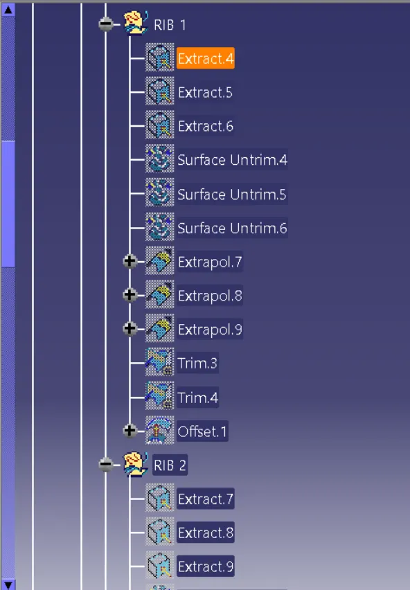
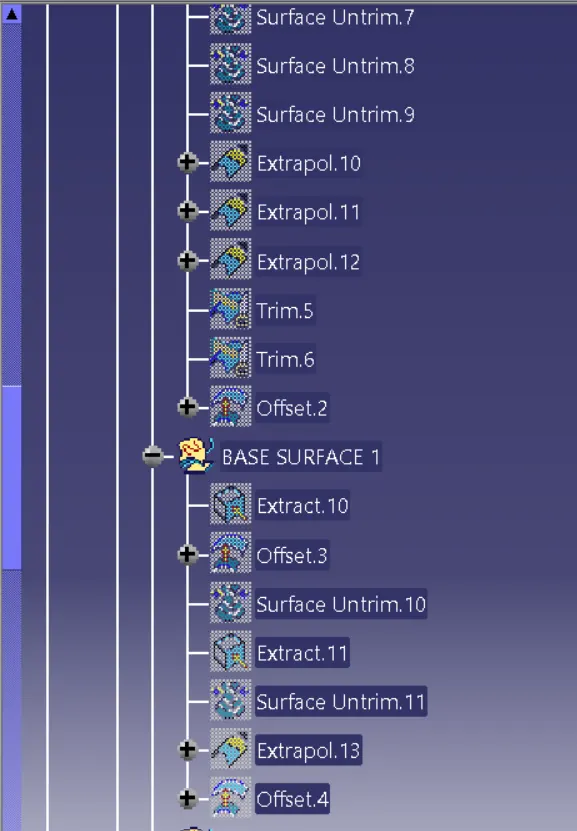
Class B surface is created by extracting each wall and untrimmed walls extrapolating the walls and then trimming the extra surfaces and offsetting it to a certain value based upon the thickness of the component where it is 2.5 mm. The offset surface will be the B-Surface.
DEVELOPNMENT OF CLASS C SURFACE:
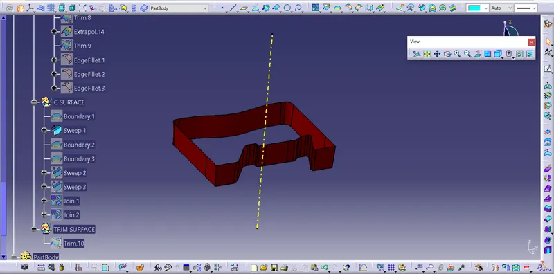
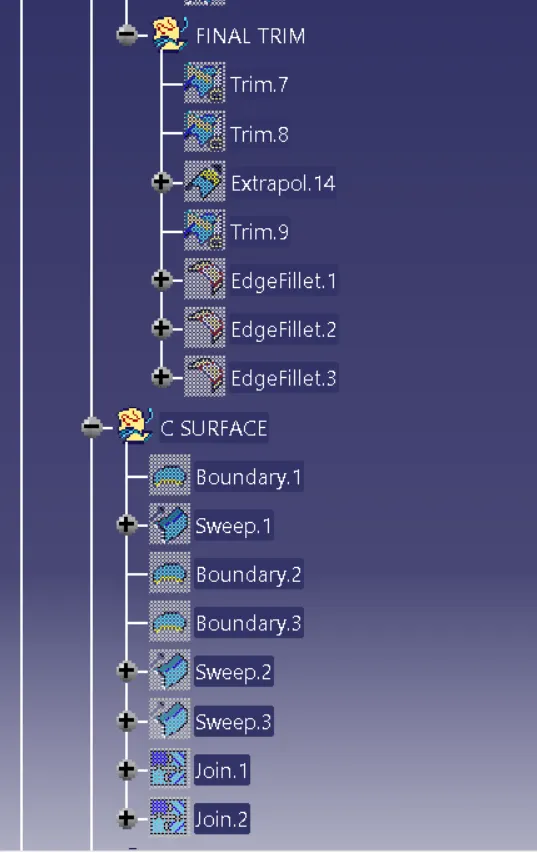
This surface is obtained by sweeping the boundaries of the class A surface along the tooling Axis direction, it connects A and B surfaces
Using B and C surfaces a closed surface is formed by trimming the extra surfaces
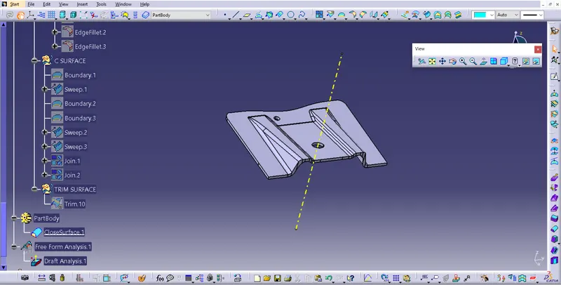
The Final trim part is converted into a solid component using closed surface command.
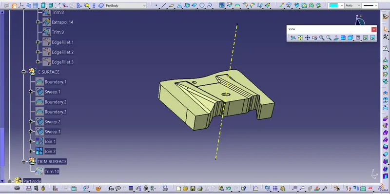
The Final trim part is converted into a solid component using closed surface command.
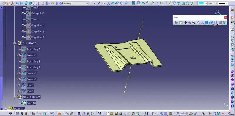
CLOSED SURFACE PLASTIC MODEL:
CONCLUSION:
Base bracket plastic component using class A Surface have been successfully created and draft analysis have also been performed for the same.
FEATURE TREE MANAGER:
VIEW ORIENTATION: