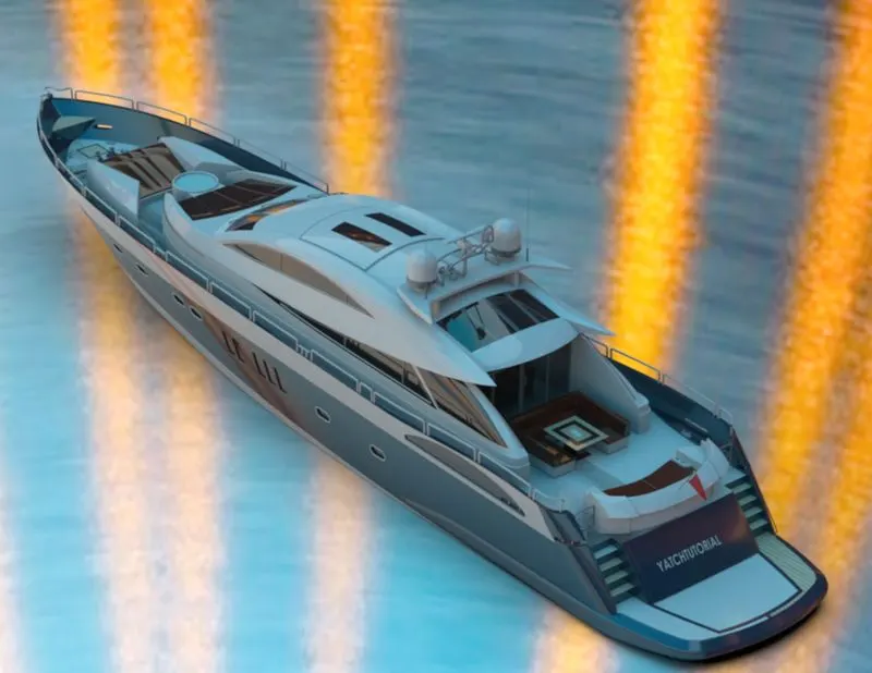
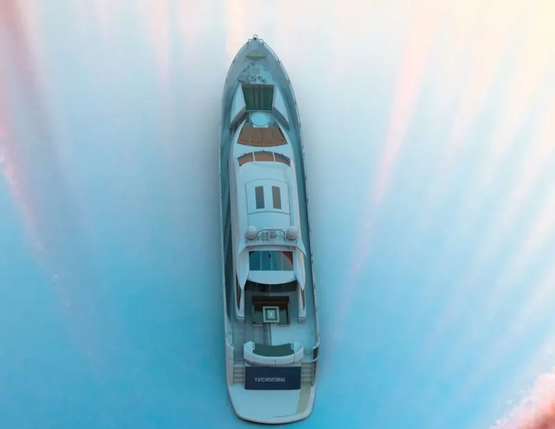
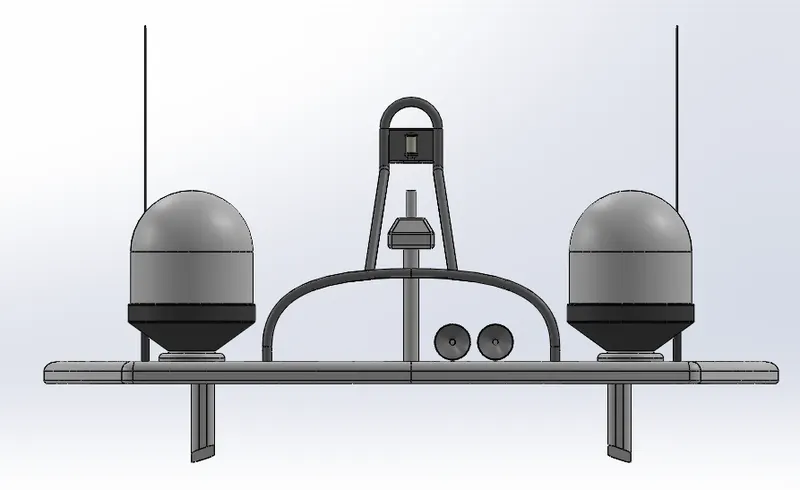
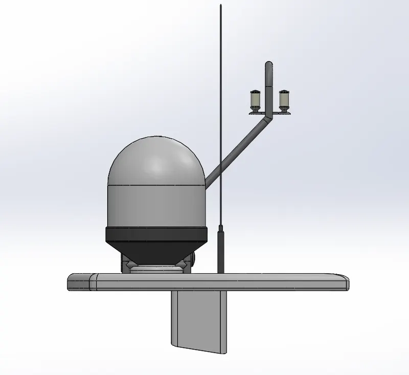
Radar Mast & Final Assembly of Yacht
SKILL LYNC
PROJECT REPORT
MODELLING OF SUNSEEKER PREDATOR YATCH
BY
S.JAMEEL AHMED
OBJECTIVE
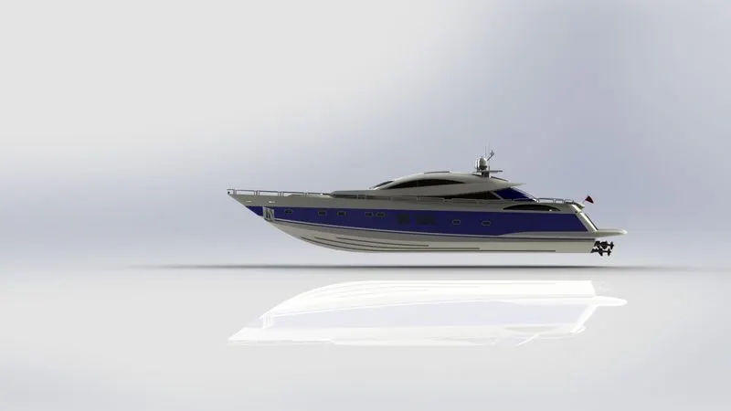
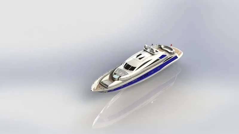
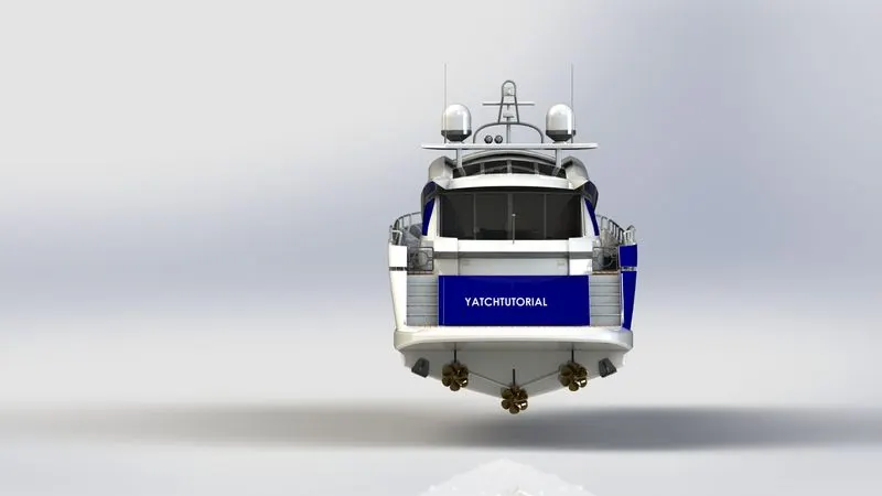
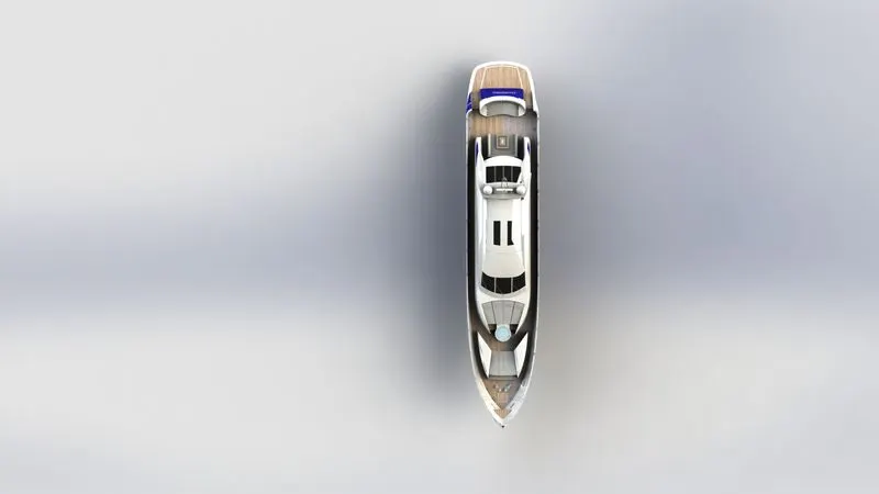
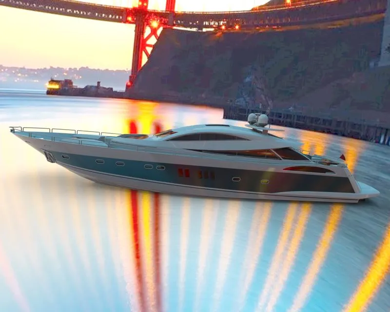
The objective of the project is to design and model all the parts of an American predator yatch and assembling it to create the photo realistic rendering of the yatch
INTRODUCTION
In this project the American predator yatch was taken as a conceptual model, to understand the 3D modelling methodology of solid modelling and surface modelling. Each and every part of the yatch was designed and modelled parts were assembled by adding proper mates and constraints to create the photo realistic rendered image of the yatch
Photo view 360 is a solidworks add in that produces photo realistic renderings of solidworks models. The rendered image incorporates the appearances, lighting, scene, and decals included with the model
Solidworks visualize is a photo realistic rendering tool that utilizes our cad data to create magazine quality images or commercial quality animation
DESIGN REQUIREMENTS
The essential requirements of a good product design are listed as follows:
- Product must optimally perform its main function.
- It must be easy to repair at a low repair cost.
- It must be very reliable to use
- It must follow principle of aesthetics
- It must be a durable one.
- It can be easily produced in large numbers at minimum production cost.
- It must also be compact
DESIGN APPROACH
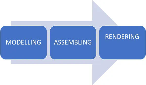
DESIGN METHODOLOGY
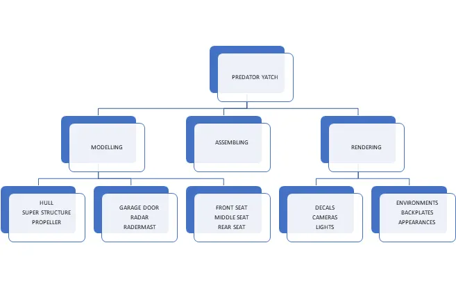
TYPES OF COMMANDS AND ITS EXPLANATIONS
Sketch -create the sketches and decide how to dimension and where to apply relations.
Feature -select the appropriate features,such as extrudes and fillets, determine the best features to apply , and in what order to apply those features must be decided
Surfaces- surfaces are a type of geometry that can be used to create solid features.
Assembly- select the components to mate and the types of mates to apply
SKETCH
Creating a modeling usually begins with a sketch. From the sketch , we can create features. We can combine one or more features to make a part. Then we can combine and mate the appropriate parts to create an assembly. From the parts or assemblies, we can then create drawings.
3-D SKETCH
When sketching in 3D, we can snap to the major directions, x,y,z and constraints are applied along x,y,z respectively. These are constraints to the global coordinate system
When sketching on a plane, we can snape to the horizontal or vertical directions in the plane , and constrains are applied to the horizontal and the vertical. These are constrains to plane, planar, face, etc.
FEATURES
Lets discuss what are the features and properties used in the entire model to design different parts
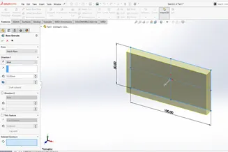
- EXTRUDE:
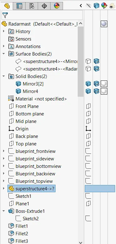
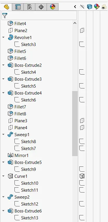
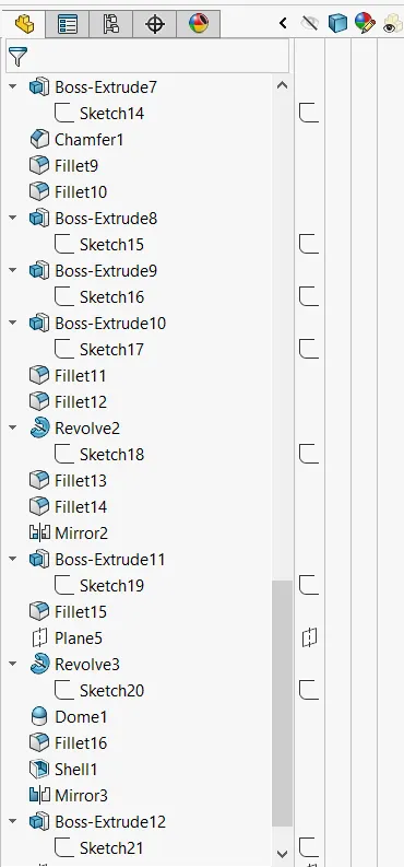
Using the solidworks extrude feature we can able to covert 2D sketch in to a 3D model with respect to its geometry in a normal direction . first we need to draw a fully closed 2D sketch and then extrude it by fully defining its starting point, ending point, contour and direction of extrusion.
- REVOLVE:
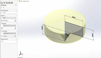
The revolve feature is used to revolve a 2D sketch along an axis or centerline to make its 3D model.A 2D sketch is drawn and revolved by selecting its reference line for axis of rotation and defining the angle of rotation.
- SWEEP:
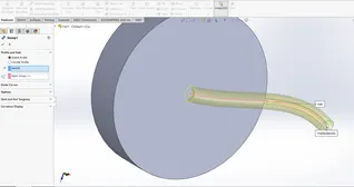
A sweep tool used to sweep a closed 2d sketch a path . this tool is generally used for curved tubes and bars . a closed loop and a path to sweep are required and we need to creat a profile for the sweep as well the path to end by this we can able to complete it.
- FILLET:
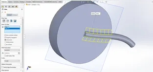
A fillet is a tool used to round an edge, vertex and faces on both inside and outside of a 2D or 3D model . need to select fillet type for our model and location, radus of the fillet needs to be defined.
- CHAMFER:
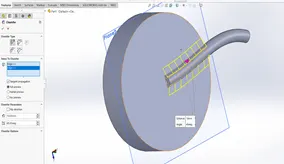
A chamfer is used to remove a edges by creating a sloped edges , vertex or face . distance and angle of the chamfer are needs to be defined .
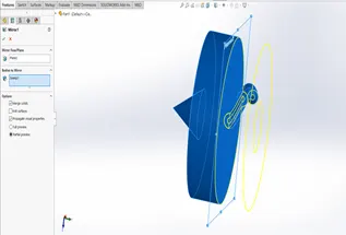
- MIRROR :
Mirror tool is used to copy the 2d or 3d about the center or reference line . as well as we can able copey the object by using the plane also . we can have either only the mirrored obect or both the orginal and mirrored objects.
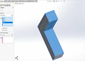
- SHELL:
The shell tool hollows out a part, leaves open the faces you select and creates thin walled features on the remaining faces . if you do not select any face on the model, you can shell a solid part, creating a closed , hollow model . you can also a model using multiple thickness.
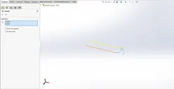
- PROJECTED CURVES:
A projected curve is a 3d curve that represents the intersection of two extruded surfaces of two sketches on intersecting planes.
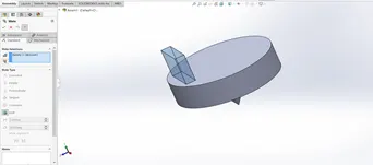
- MATES:
Mate operation is the basic tool for assembling the parts . there are various mate operations such as coincident ,parallel, perpendicular, tangent , concentric, lock , etc . we can mate two faces by defining distance or angle between them.
SURFACE MODELLING
Surface modelling is a method of creating planar or non planar complex geometry which has zero thickness. This zero thickness geometry is known as surface. The surfaces are generally used to create models of complex shapes. We can also extract a surface from a solid models . we can also extract a surface from a solid model using the tools available for surface modeling.
SURFACE COMMANDS
- Lofted surfaces- creates a lofted surface between two or more profiles or sketches. Specify start and end constraints and add guide curves to control the path shape.
- Boundary surface- the boundary surface feature lets us to creat surfaces that can be tangent or curvature continuous in both directions . in most cases, this delivers a higher quality result than the loft tool.
- Extruded surface- extrudes a sketch or selected sketch contours in one or two directions two create a surface features
- Revolved surface-revolves a sketch or selected sketch contours around an axis to create a surface features.
- Swept surface- it sweeps a closed profile along an open or closed path to create a surface feature. It uses a tangent plane at the end of the path so that is normal to the swept surface.
- Filled surface- patches a surface within a boundary defined by edges , sketches, or curves. We can use constraint curves to fill surfaces and adjust resolution control to improve surface finish.
- Ruled surface- inserts ruled surfaces in a specified direction from edges. Tangent to surface,normal to surface, tapered to vector, perpendicular to vector or sweep can be selected . we can also trim and knit the surface and remove any connecting surfaces.
- Trim surface- it trims the surfaces where a surface intersecting with another surface, plane or a sketch
- Knit surface- it combines two or more adjacent, non- intersecting surfaces in to a single surface body. The surfaces must joint at an edge.
PART MODELLING DESCRIPTION
BLUEPRINT
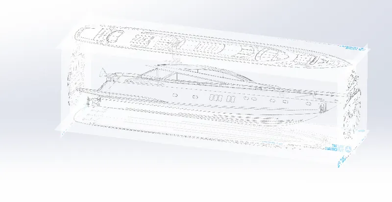
A blue print is a reproduction of a technical drawing or engineering drawing using a contact print process on light sensitive sheets. A blue print is a guide for making something, its design or pattern that can be followed. They were easier to read and fater to make.
- HULL
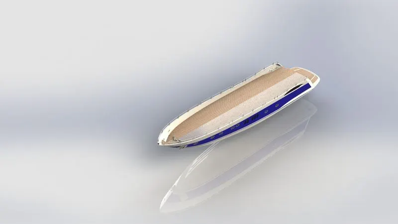
A hull is the watertight body of a ship or boat. The hull may open at the top, or it may be fully or partially covered with a deck. The line where the hull meets the water surface is called the waterline.
The hull of a ship is the most notable structural entity of the ship.to define the hull, it can be said that it is the watertight enclosure of the ship, which protects the cargo, machinery, and accommodation spaces of the ship from the weather, flooding and structural damage.
- SUPER STRUCTURE
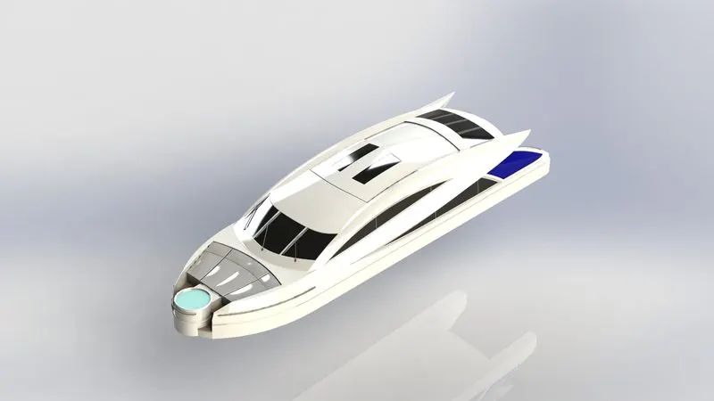
A superstructure is an upward extension of an existing structure above a baseline called ground level and it usually serves the purpose of the structures intended use . a super structure is a decked structure on the freeboard deck , extending from side to side of the ship.
- PROPELLER
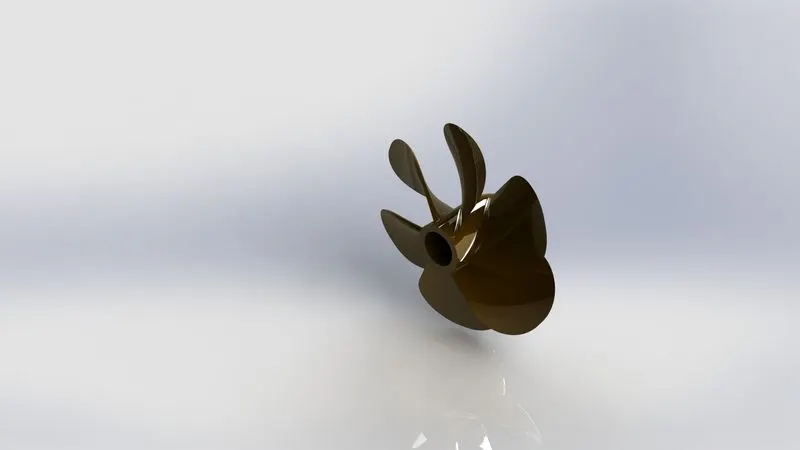
There can be one , two or three propellers. It is the most important part of the ship without which a ship cant move. So the main function of propeller is to propel the ship in the forward direction by producing thrust on water. Its working principles are newtons third law of motion and Bernoullis theorem.
- GARAGE DOOR
A garage door is a large door on a garage that opens either manually or by an electric motor . garage doors are frequently large enough to accommodate automobiles and other vechicles . the operating mechanism is spring loaded or counterbalanced to offset the weight of the door and reduce human or motor effort required to operate the door . less commonly, some garage doors slide or swing horizontally. Doors are made of wood, metal, or fiberglass, and may be insulated to prevent heat loss.
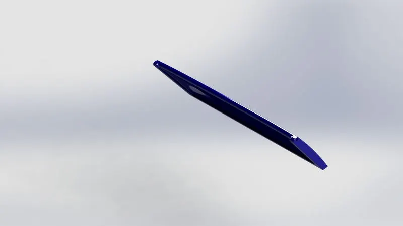
- RADAR
Marine radar are x band or s band radars on ships, used to detect other ships and land obstacles, to provide bearing and distance for collision avoidance and navigation at sea. They are electronic navigation instruments that use a rotating antenna to sweep a narrow beam of micro waves around the water surface surrounding the ship to the horizoin, detecting targets by microwaves reflected from them, generating a picture of the ships surroundings on a display screen.
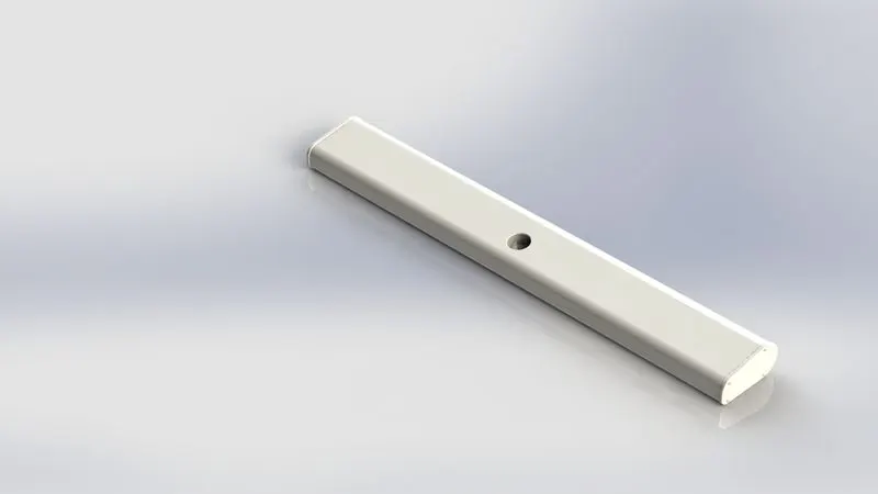
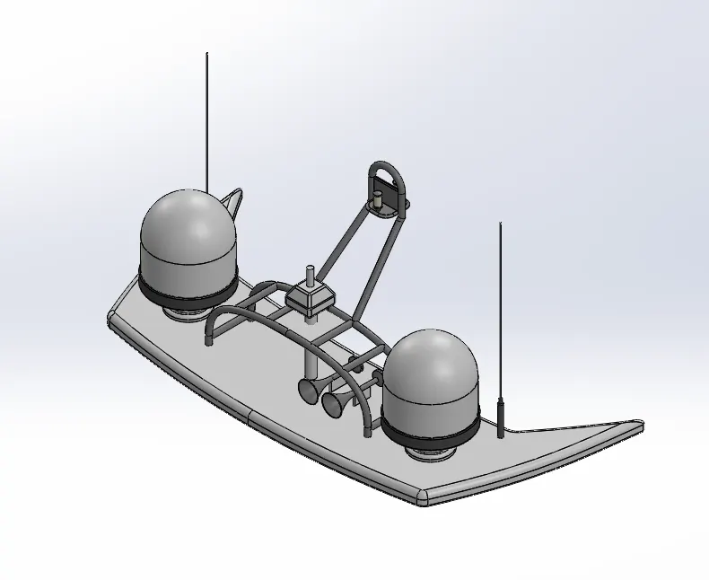
- RADARMAST
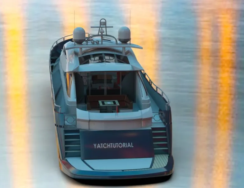
A mast is a vertical ship structure mounted on top of bridge and forward of the forecastle towards the ships bow. It accounts for the support platform for the ships derrick and hold necessary equipments such as radars, navigation light and ships horn in case of foremast.
They are made of high tensile steel with added rigidity based on the size of derricks it holds. Other than that a ships main mast is also used to hoist ships flag.
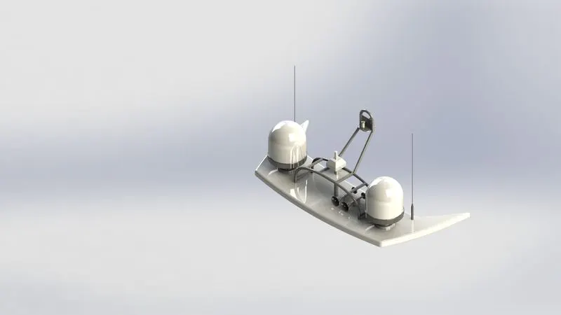
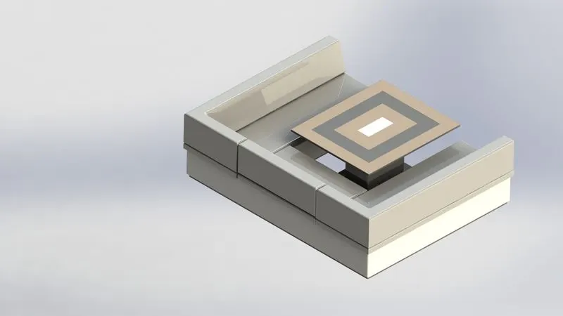
- FRONT SEAT
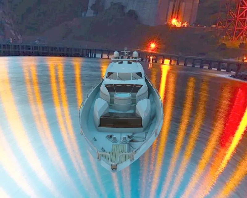
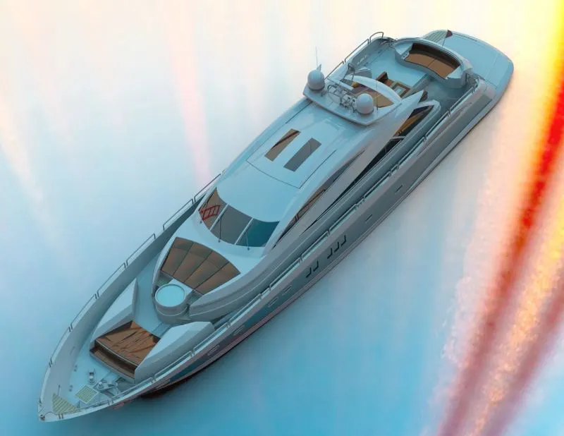
Front seats feature two connected seats that are built back to back from one and other. They have a built in storage unit underneath them. Lounge seats can also fully recline right back to make it easier for you to kick your feet up and get more comfortable. The front seat in our model was placed before the superstructure and also it has sun pads to rest on it. Sun pads are a great way to reclaim lost space on our boat.
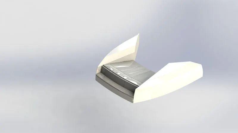
- MIDDLE SEAT
The middle seat in our model was placed just behind the superstructure. It is provided with a luxury table to dine out. It can also be used to have casual meetings with co passengers.
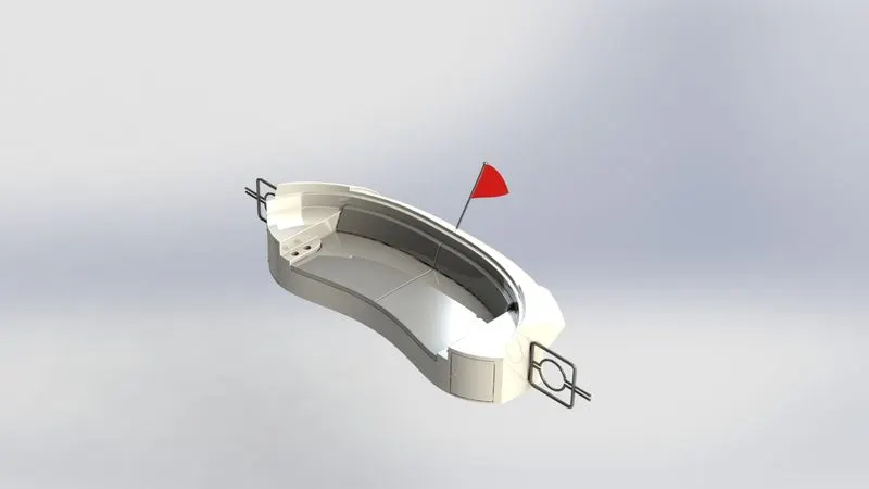
- REAR SEAT
The rear seat was placed at the end of the deck surface. The rear seat consist of locker racks and steel doors for our stairs. The flag was also placed behind the rear seat since it’s the end part of our yatch. To have a nice view from the yatch while having a drink the rear seat was also provided with a slots to rest the glass or mug.
ASSEMBLY
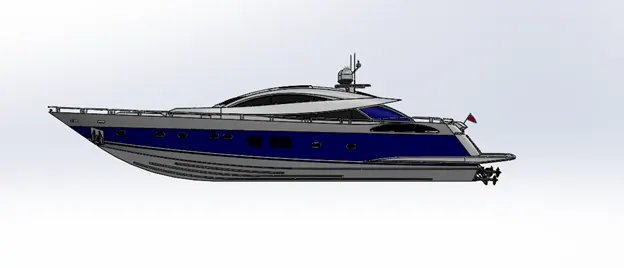
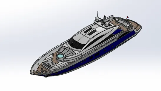
An assembly is a document in which parts, features, and other assemblies are mated together. The parts and subassemblies exist in documents separate from the assembly. For example, in an assembly, a piston can be mated to other parts, such as a connecting rod or cylinder. This new assembly can then be used as a sub assembly in an assembly of an engine . the extension for a solidworks assembly file name is SLDASM.
ASSEMBLY PROCEDURE
- Import all the parts manually by using insert components option.
- Then fix the hull part by applying the coincident mate to the top, right and front planes of the assembly and hull respectively
- Then for each part apply the necessary mates requires by the blueprint using coincident mates, angle mates, distance mate etc.
- Advanced mate was also used where ever required.
RENDERING
Rendering of the solidworks model is done using photo view 360 and solidworks visualize.
PHOTOVIEW 360
Is a visualization and rendering solution included with solidworks. Providing a highly interactive environment for viewing design as well as for creating photo realistic renderings it can be used to showcase our designs.
SOLIDWORKS VISUALISE
Its provides a suite of standalone software tools that combine industry leading rendering capabilites with visual design oriented features and workflows, allowing easy and fast creation of visual content that communicates a design vision , passion, and emotion.
Some renders are fast but output low quality images. Some produce great quality but take six months to learn. Others are easy to use, but take four hours to render an image.solidworks visualize provides the right combination of quality, speed, and ease of use and is the best renderer.