Door Arm Rest Week 8 Challenge
DOOR ARM REST DESIGN :
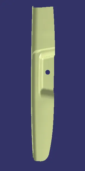
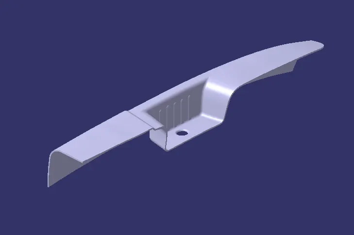
The objective of this assignment is to create a solid part of Door Arm Rest from the Class A Surface provided with proper Draft Angle and perform the Draft Analysis on both the Class A Surface and the Solid part.
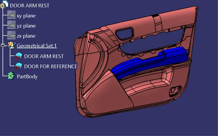
DRAFT ANALYSIS :
- Before creating the Class B and Class C Surface we need to perform the Draft Analysis on the class A surface.
- For creating the Tooling Axis first we need to know the part that would be formed in the core part and cavity part.
- Deciding the core and cavity side it will give the Tooling Direction.
- The Tooling Axis is created in order to check the Draft given on the faces.
- Draft should be present on both side of the surface in order to make the part manufactureable.
- So to check the manufacturability of the component Draft Analysis is performed on the Class A Surface and the Solid component.
- To perform the Draft Analysis we first need to create the Tooling Axis.
CREATION OF TOOLING AXIS :
- In order to create the Tooling Axis first we need to decide the point through which the Axis has to pass.
- As there is hole in the part so the tooling axis must pass through the centre of the hole so that the hole can be created during plastic molding process and no extra manufacturing process is required to create the hole.
- So we create a point at the centre of the hole and a Axis System is created through the point.
- Now we have two surfaces which are tapered and the draft angle present between them must clear the draft analysis test.
- To create the Tooling Axis we have to bisect the two lines which follows the taper profile.
- To do so we have two perpendicular planes and at first one of the perpendicular plane which is perpendicular to both the side walls is intersected to create the section line and through that we have two lines that must be checked for the clearance of draft analysis.
- So the two lines are bisected to create a bisecting line and also by visualization the upper face is in 45 degree with the bisected line.
- Now for the back face we have a perpendicular plane and the plane is intersected with the back face to create section line which is used to check for the draft analysis.
- A line is drawn following the profile of the taper line and a random line is drawn from the point defined earlier and angle between them is given as per the design rule in order to clear the draft analysis test.
- Now using the above two lines we create our Tooling Axis by bisecting both the lines.
- This gives the Tooling Axis for the part.
TOOLING AXIS FOR THE RIBS :
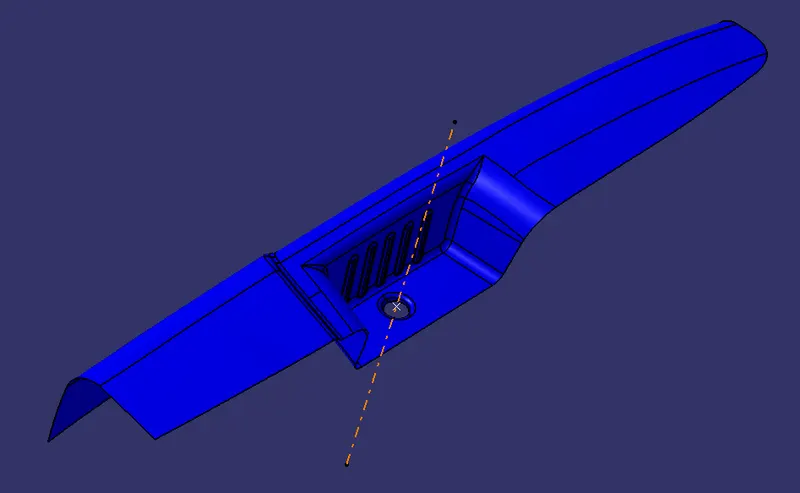
- We have Ribs on one of the face of the component which cannot be manufactured through the above defined Tooling Direction.
- So in order to manufacture these ribs we need to provide a Side Core.
- In order to actuate the Side Core a Tooling direction must be defined and a Tooling Axis should be created.
CREATION OF TOOLING AXIS :
- In order to create the Tooling Axis for the Side core we need to extract the Face on which the Ribs are present.
- Then we create a point at the centre of the surface to create our Tooling Axis.
- A line is created perpendicular or normal to the surface and passing through the point created.
- This line becomes our Tooling Axis for the Side Core.
THIRD TOOLING AXIS :
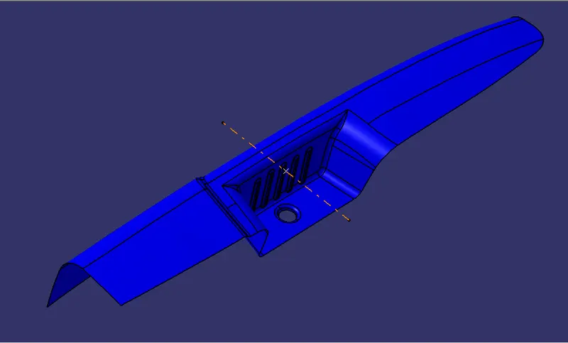
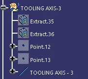
- In order to create the Tooling axis in the perpendicular direction to the part Tooling Axis we created two centre points at the parallel surface to our main Tooling Axis.
- Then our Third Tooling axis is created by drawing a line between the two points and the line is perpendicular to faces.
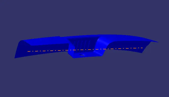
DRAFT ANALYSIS :
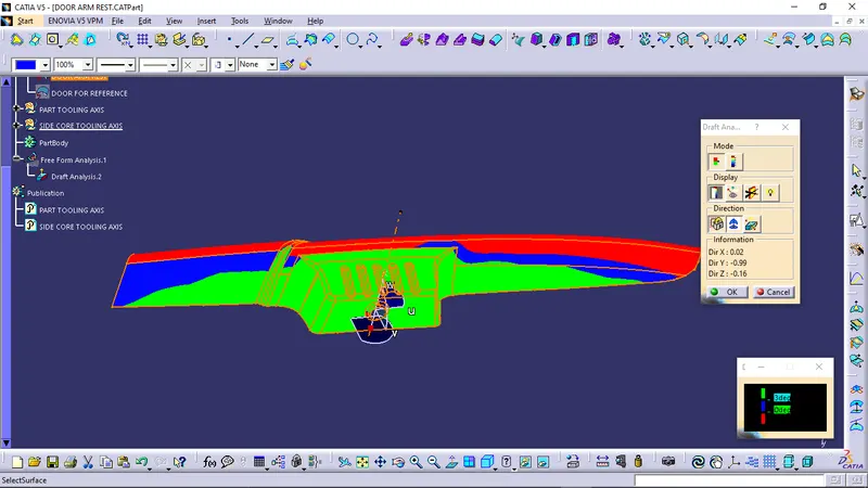
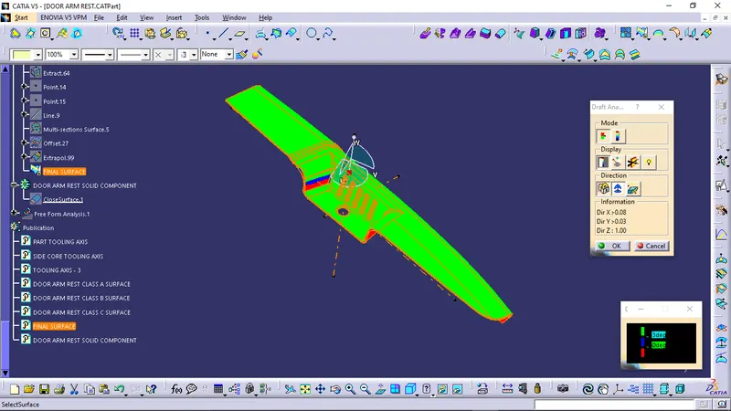
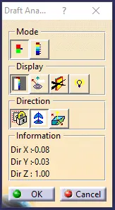
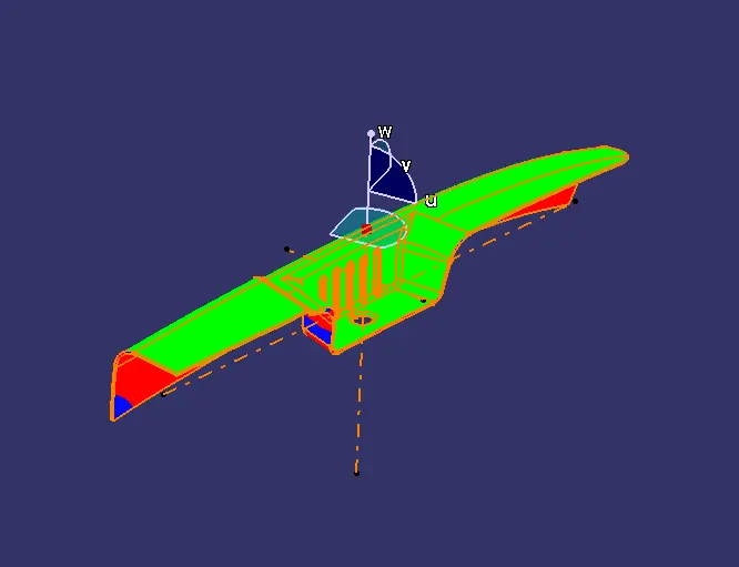
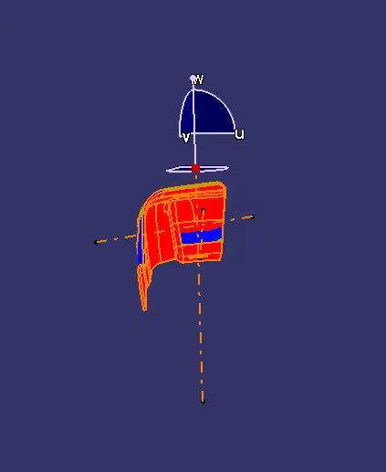
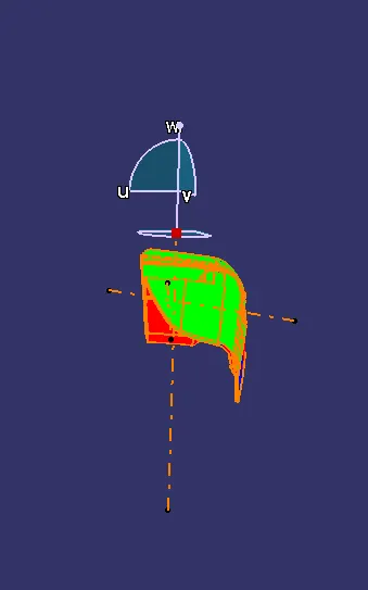
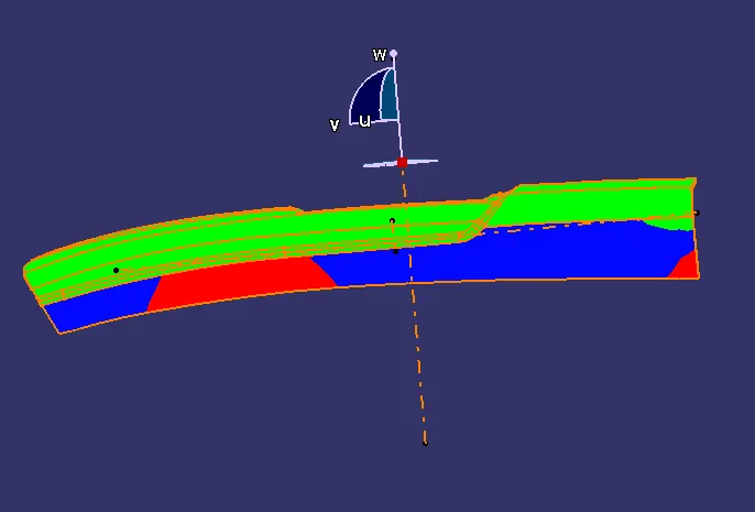
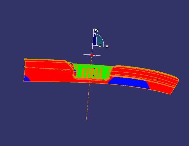
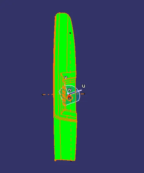
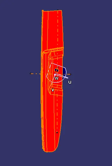
As the Tooling Axis are created for both the component the Draft Analysis is carried out to check that all the faces clear the Draft Analysis test.
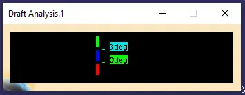
DESCRIPTION OF THE COLOR VARIANT USED IN THE DRAFT ANALYSIS :
1. GREEN COLOR : Green color is assigned for having draft angle more than 3 degree.
2. BLUE COLOR : Blue color is assigned for having draft angle between 0 to 3 degree.
3. RED COLOR : Red color is assigned for having Negative draft angle.
DRAFT ANALYSIS OF THE CLASS A SURFACE :
USING PART TOOLING AXIS :
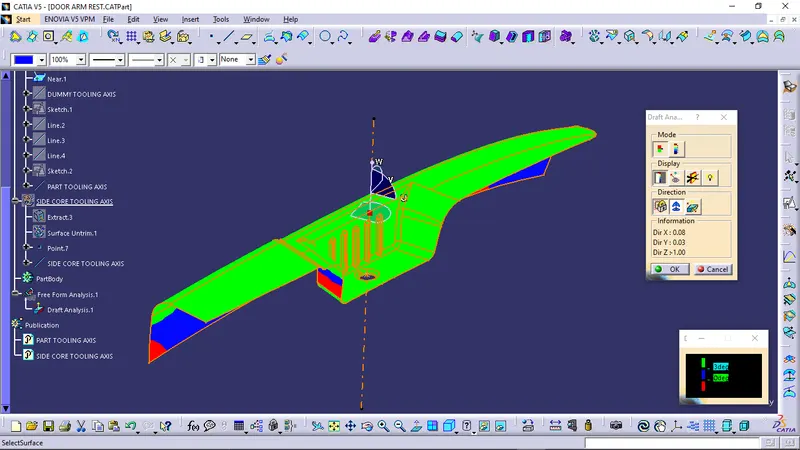
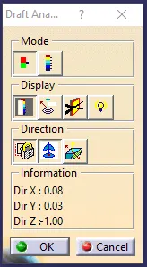
USING SIDE CORE TOOLING AXIS FOR THE RIBS :
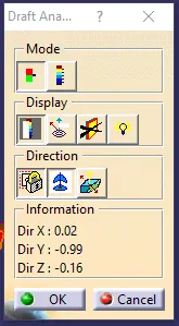
Here the Draft analysis is performed in order to check that proper draft angle is present in the ribs or not so that the Ribs can become manufacturable and would be manufactured using the Side Core.
DRAFT ANALYSIS ON THE FINAL PART :
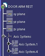
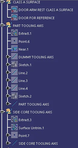
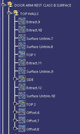
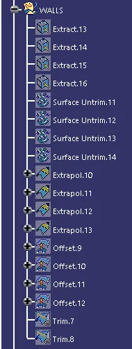
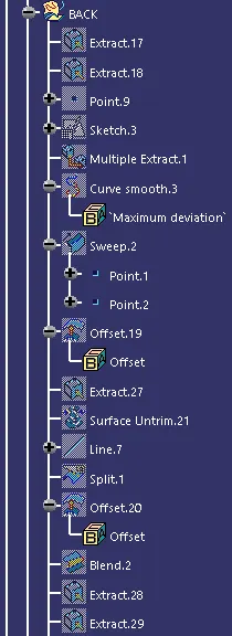
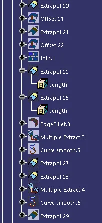
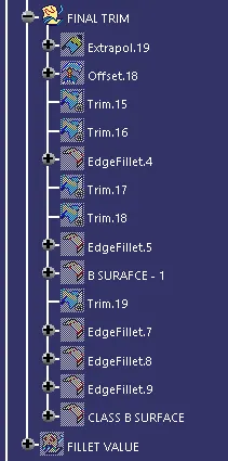
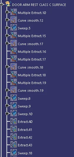
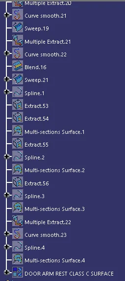
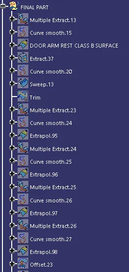
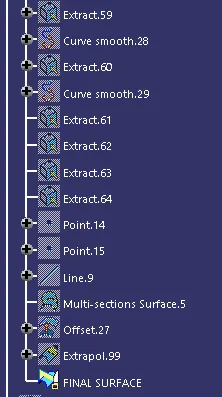
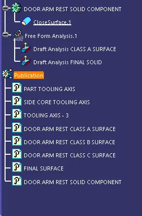
TREE STRUCTURE :
DIFFERENT VIEWS OF DRAFT ANALYSIS ON THE FINAL PART :
ISOMETRIC VIEW :
FRONT VIEW :
BACK VIEW :
LEFT VIEW :
RIGHT VIEW :
TOP VIEW :
BOTTOM VIEW :
DIFFERENT VIEWS OF THE SOLID PART :
ISOMETRIC VIEW :
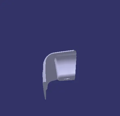
FRONT VIEW :
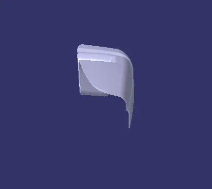
BACK VIEW ;
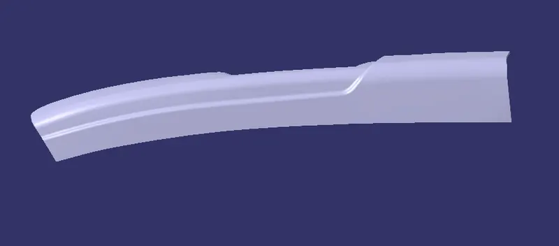
LEFT VIEW :
RIGHT VIEW :
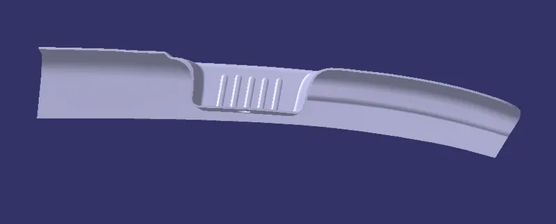
TOP VIEW :
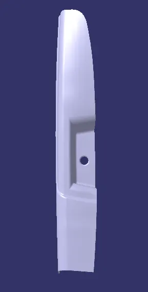
BOTTOM VIEW :
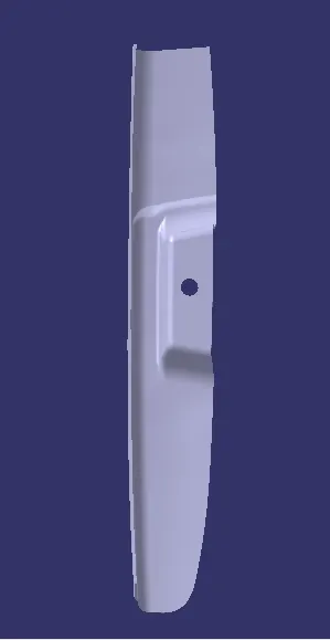
DIFFERENT VIEWS OF THE SURFACE PART :
ISOMETRIC VIEW :
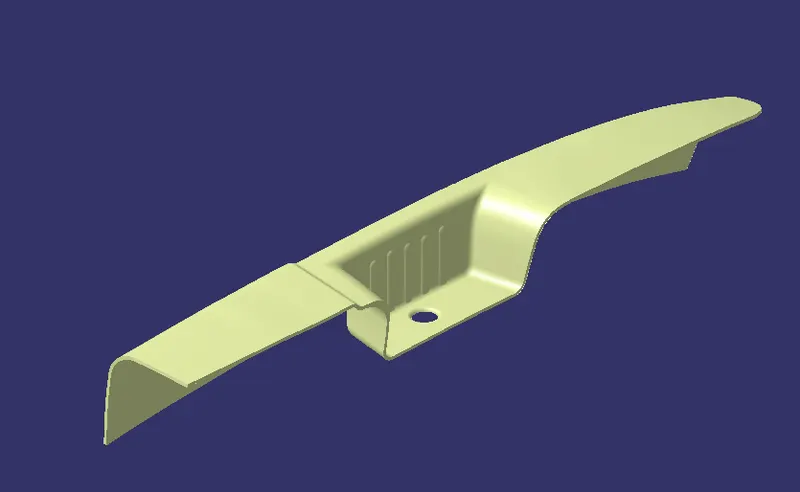
FRONT VIEW :
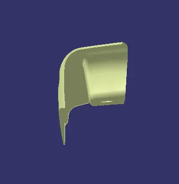
BACK VIEW :
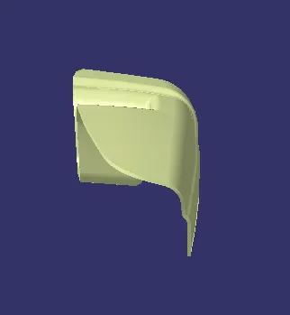
LEFT VIEW :
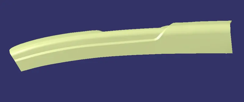
RIGHT VIEW :
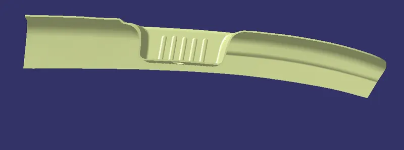
TOP VIEW :
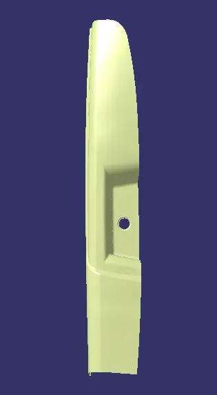
BOTTOM VIEW :