Door Arm Rest Week 8 Challenge
AIM: to create door arm rest by using given class a surface
DOOR ARMREST: it is an interior part that is generally made of thermoplastic polyurethane which is manufactured by injection moulding
TOOLING AXIS :
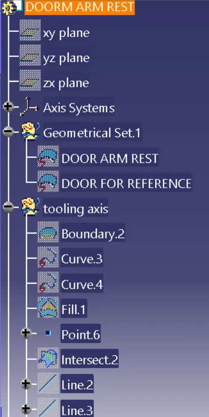
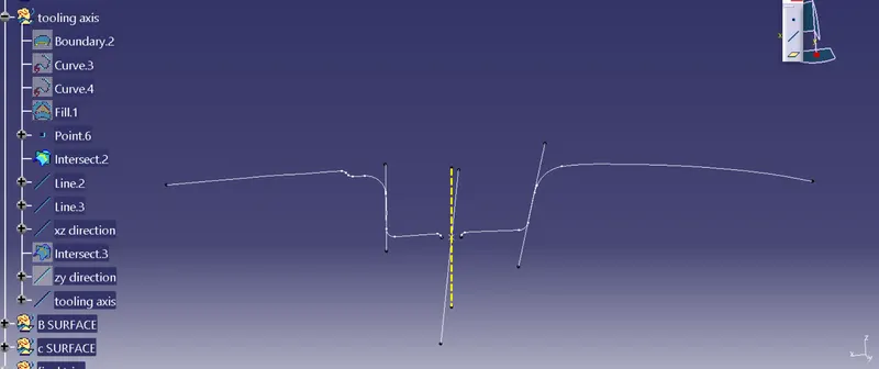
first create an intersection on the xz plane take the two inclined lines, and create two lines on those inclined lines make everything else as construction other than these two lines. select these two lines and then create a bisection line, this line will be axis along xz direction
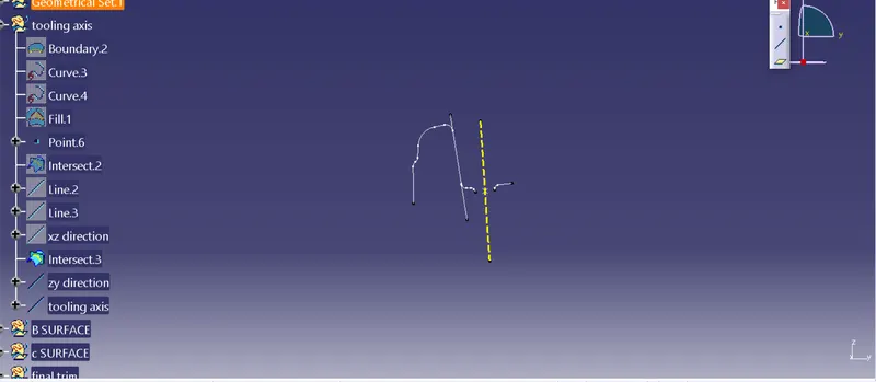
create another intersection in yz direction and make a point on the extracted base surface, select the inclined line and make a new line using two points, since we don't have another line on the opposite side create a verticle random line from the point and dimension it 6 degrees from the other verticle line that we created earlier name it as tooling axis yz direction
now create a bisecting line for both xz and yz axis and that will be the tooling direction chab=nge the physical characteristic and publish it
CLASS B SURFACE :
BASE
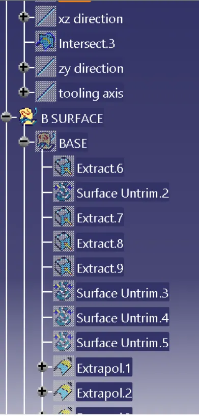
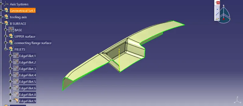
make a new geometrical set needed surface is extracted and then untrimmed, it is then extrapolated and then an offset of 2.5 mm outside the class a surface is given to it this procedure is done to all the other needed surface .
UPPER SURFACE :
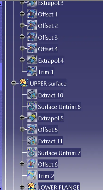
the same above procedure is done to get the upper surface. Then the upper surface and base are trimmed together and a new trimmed surface is formed
CONNECTING SIDE FLANGE :
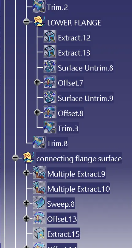
The same procedure is done to get above side surfaces and then these surfaces are extrapolated. after extrapolation an offset of 2.5 mm is given to it.
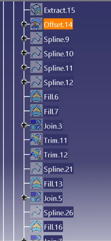
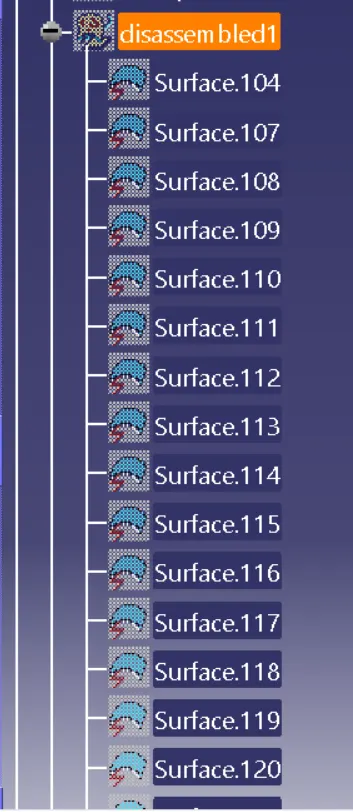
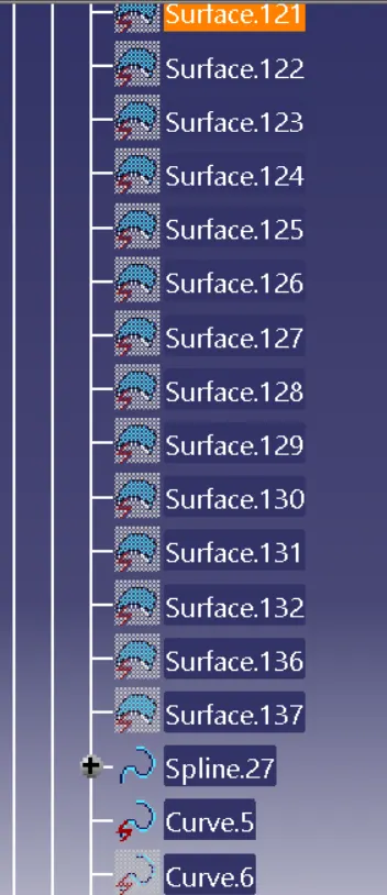
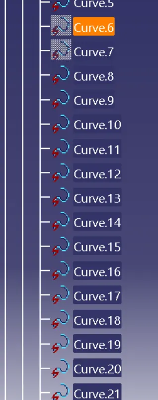
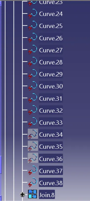
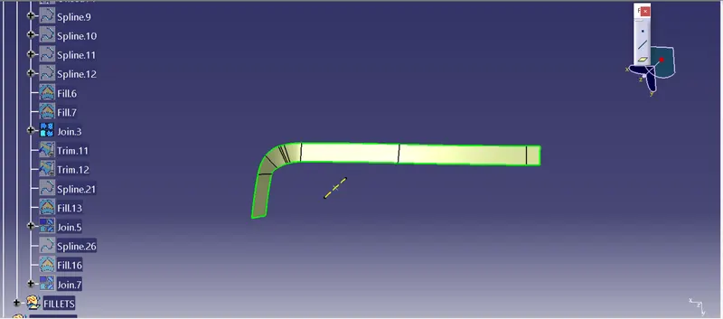
to create the region in between this use multi extract to extract the required edge of A surface and then use disassemble command, now check for self-intersecting surfaces if found any delete them, use the spline curve option and create new curves in the disassembled surface using tangent point and at last join all fill and disassembled surfaces together.
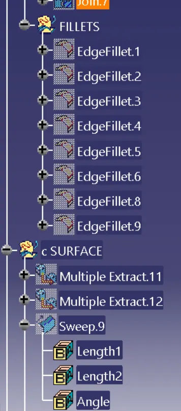
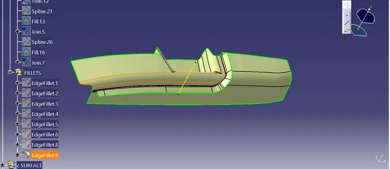
use the above-joined surface to trim the connecting flange. measure the fillet radius on A surface and use edge fillet on SHARP EDGES OF B surface. This is how we create b surface
in-between connecting flange
C SURFACE CREATION
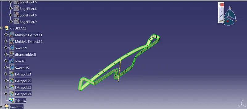
These surfaces are created by first multi extracting the outer edge of A surface and the swept along the A surface,check if there are any self-intersecting parts if there, are use disassemble command and then delete those surfaces. then use spline curve command and create new tangent spline curves on those surfaces use fill command to create new surfaces. use join command to join disassembled surfaces and fill surfaces and make a new surface then extrapolate both ends.
do this for other side and extrapolate that surface to use trim command and trim both surfaces and c surface is created
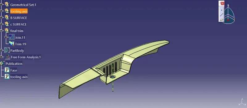
Now the c surface is joined with a surface using join command and final part is created
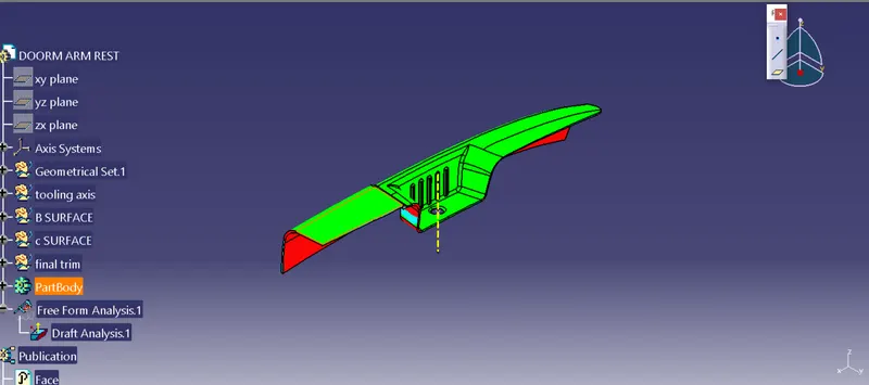
draft analysis
by using the tooling direction perform the draft analysis by moving the axis system over the tooling axis , lock the datum and then click on the surface and we will get the draft analysis where nominal draft angle is 3 degree
SOLID BODY
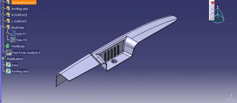
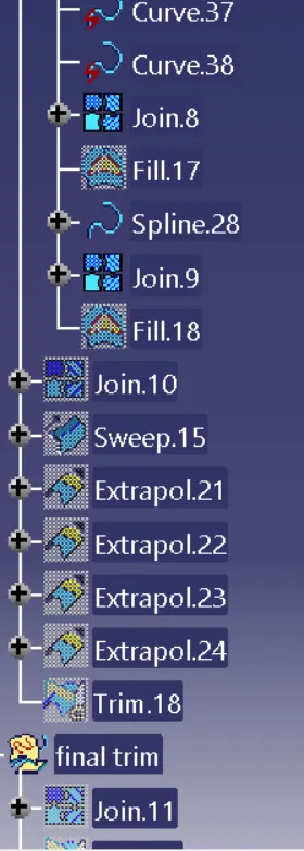
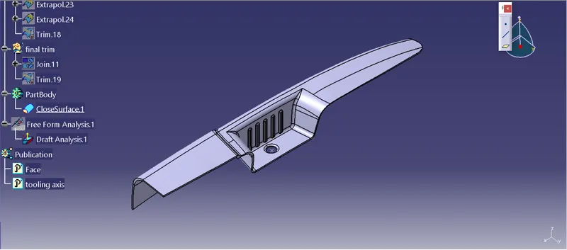
FEATURE TREE