Door Arm Rest Week 8 Challenge
DOOR ARM REST- PLASTIC PART CREATION
Objectives:
- To define a tooling axis for the class A part surface given.
- To model the Class B, class C surfaces using surface commands
- To make a completely solid body from surfaces
- To Conduct draft analysis on the solid part
Software used: DS CATIA P3 V5- GENERATIVE SHAPE DESIGN, PART DESIGN WORKBENCH
Introduction: This project involves the design and analysis of an interior plastic surface using Catia. The door armrest is one of the aesthetic surfaces in interior trim that required proper surface texture. Here we create the solid part of the armrest from a class A surface by using surface generation methods built in Catia. And make the part feasible enough for the molding process as per the industrial standards provided. Also analyzing the requirement for additional manufacturing techniques like the usage of side cores. By the end, The class B and C surfaces will be made with the proper thickness and will convert surfaces into a complete solid body.
Design methodology/ Approach:
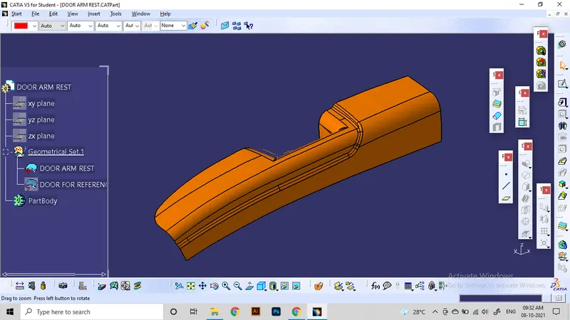
Given part:
Step 1: Creation of the tooling Axis
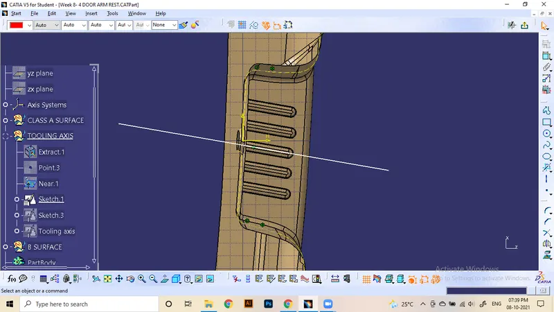
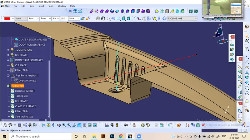
- The suitable area to define the tooling axis is considered at the pocket area of the surface part
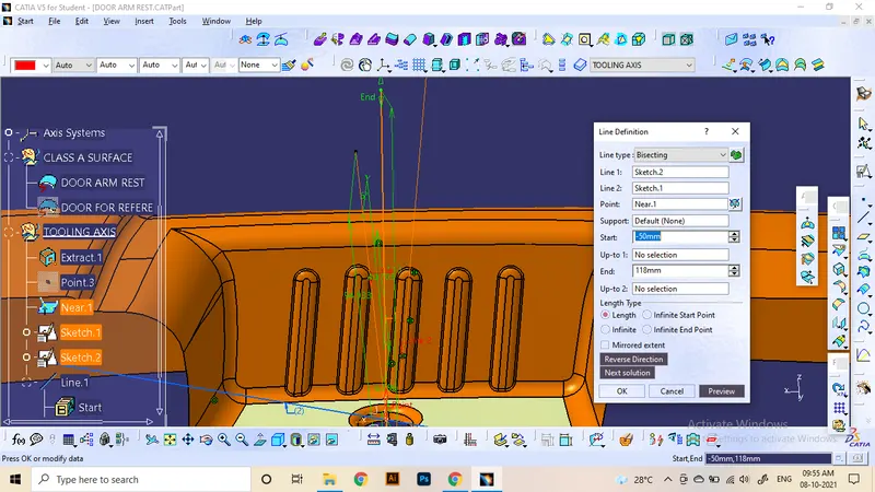
- Creation of the axis is using the positioned sketches and bisecting method
- It requires 2 or more sketches and slight modifications in angles to currect the position of tooling axis.
- Since the sidewalls of the pocket are curved, there needs an assumed line to bisect properly.
- Tooling is created with considering the draft angle, Any problems with class A surface will create small errors in draft analysis. In this case, i have reduced maximum errors.
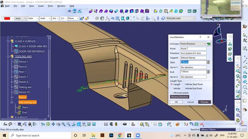
Side tooling axis:
Since the design includes of extremely curved surfaces, and complex geometries at the pocket, an additional tooling axis can be provided on the pocket area along the y axis considering the application of the side core.
Initial draft analysis:
In order to fix the tooling axis, it needs to be tested for the draft angles of the exterior surfaces. Initial draft analysis is conducted on the class A surface with tooling axis as the draft direction.
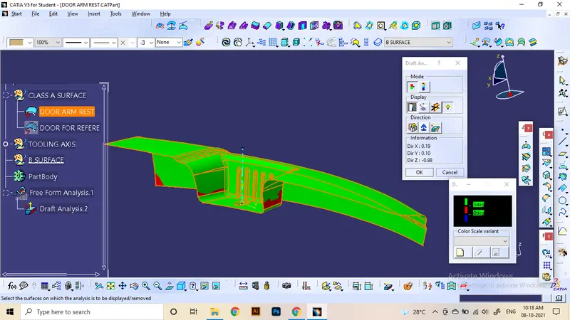
Due to the complex curvature of wall surfaces in class A, some areas are providing the draft angle as 0-3 degrees. All other areas passed in the draft analysis check.
Step 2: Class B surface generation:
In this specific part, The class A part can be divided into 3 main sections for convenience in modeling. There will be 2 continuous surfaces and one secondary surface which connect between the other two using fillets.
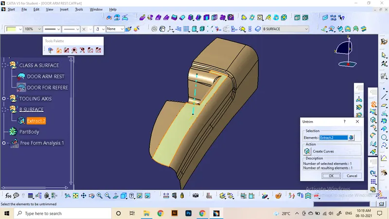
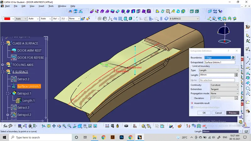
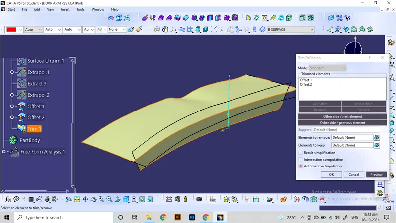
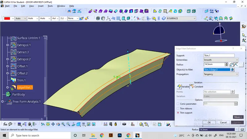
All surfaces needs to be untrimmed, extrapolated and offseted to make the patches for the class B surface.
First half:
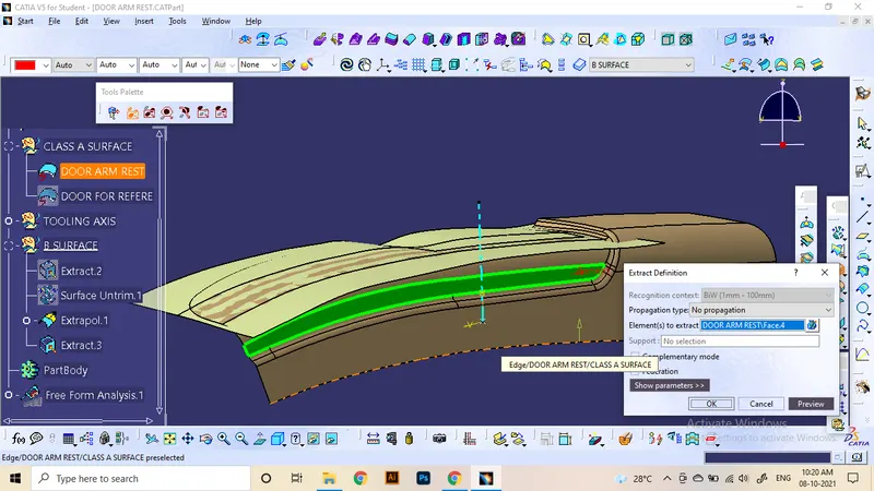
Second half:
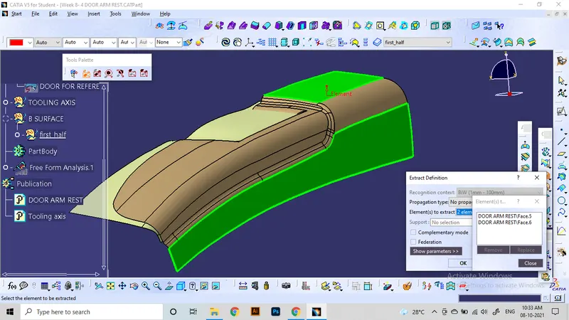
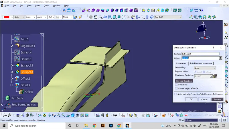
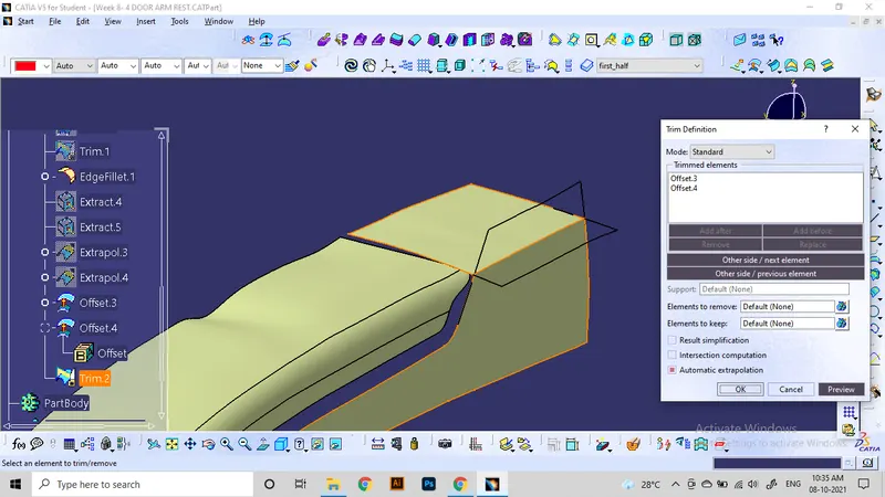
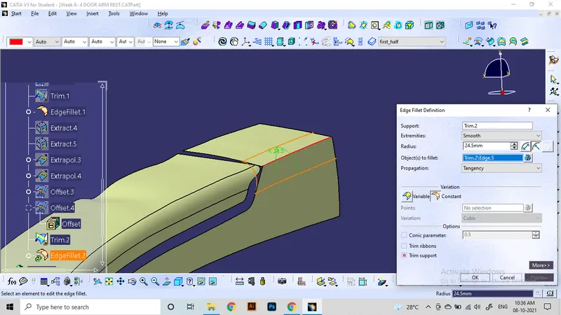
Fillet surface: To connect between two surfaces we need another one which crossed those two. It can be made using a inclined line between those 2 surfaces and sweeping them along the Fillet central line of the class A.
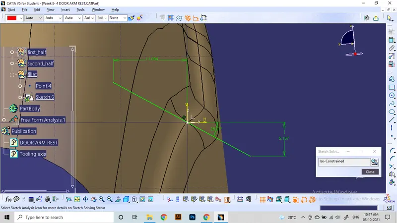
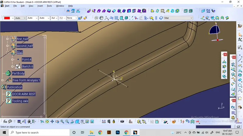
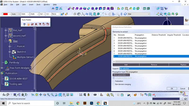
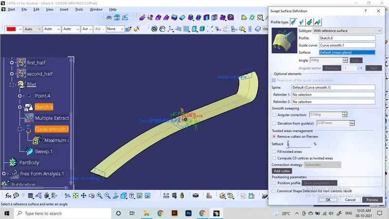
Similarly, make a surface from extracting the patch at top and connect with this sweep using blend.
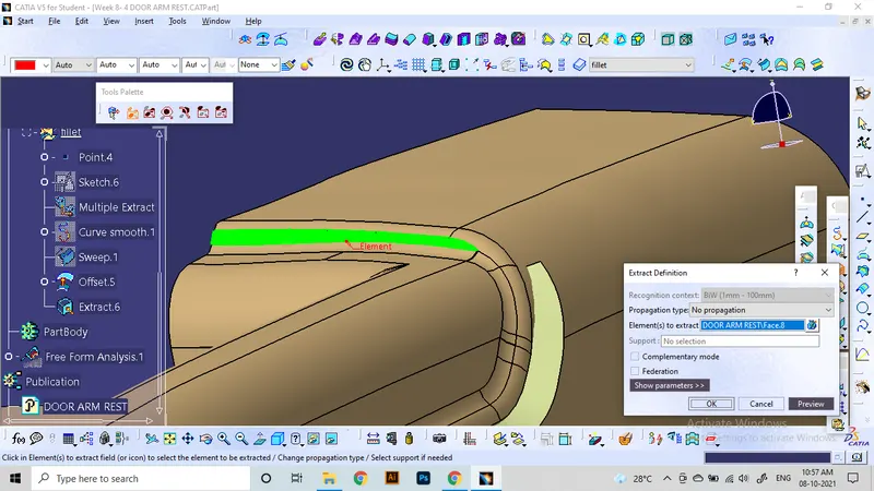
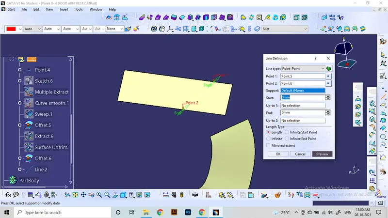
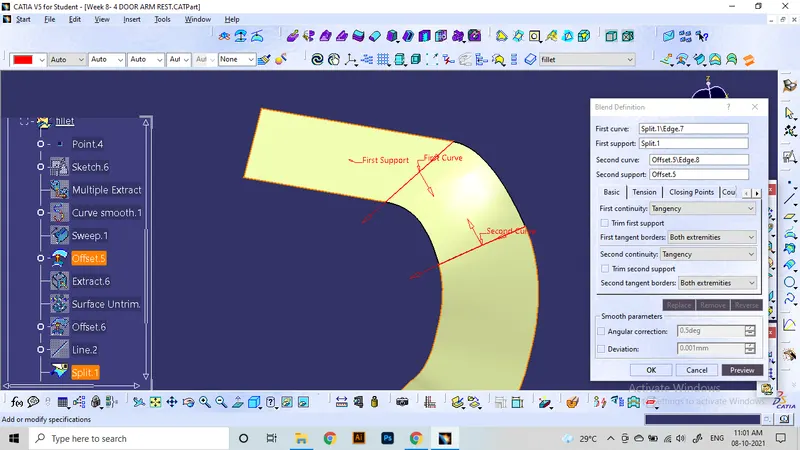
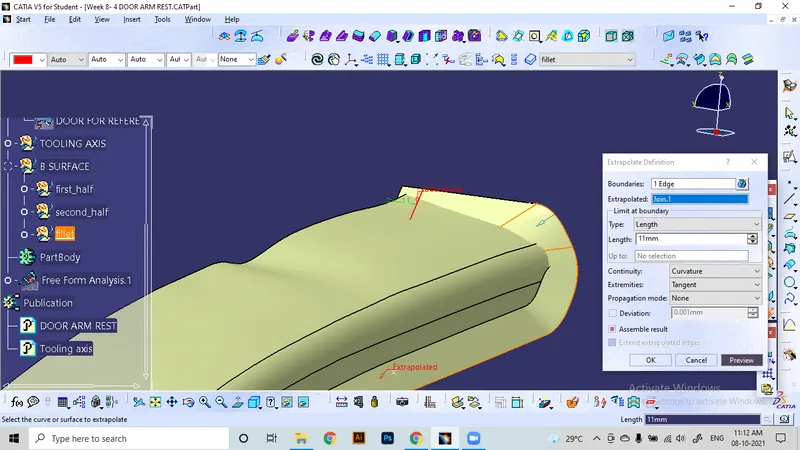
Now offset and extrapolate and trim these 3 patches together at intersection.
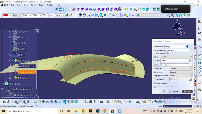
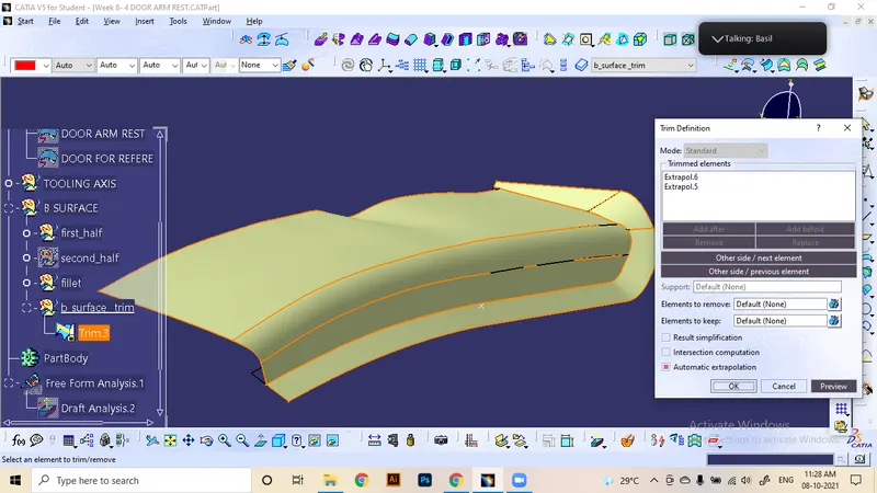
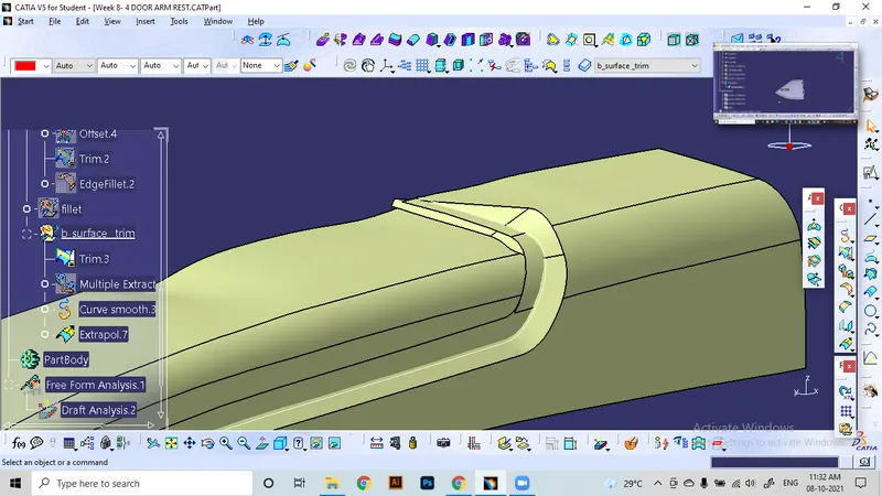
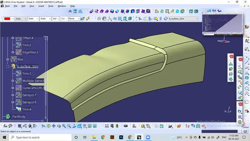
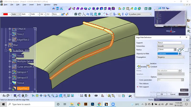
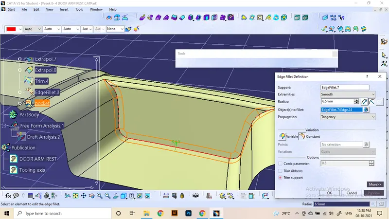
Measured fillet value from class A surface is 5mm. So fillet radius at these regions will be 5-2.5 mm.
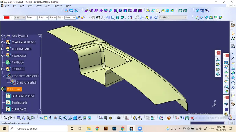
For finalizing the Class B surface, We also need the trim surfaces of the pocket.
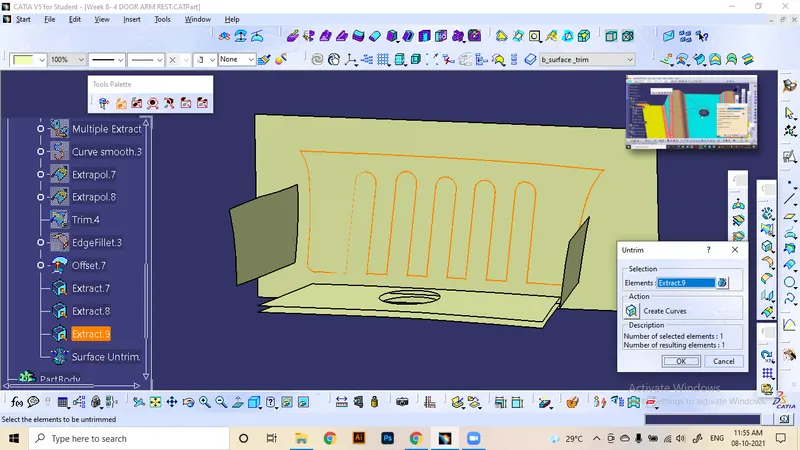
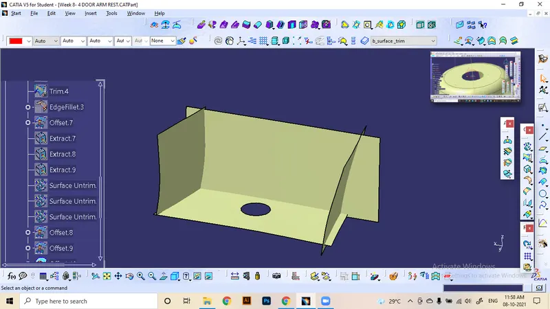
Measuring the values of fillets from class A, and applying the modified fillet values for class B. Hence, the class A and class B will have the same thickness everywhere.
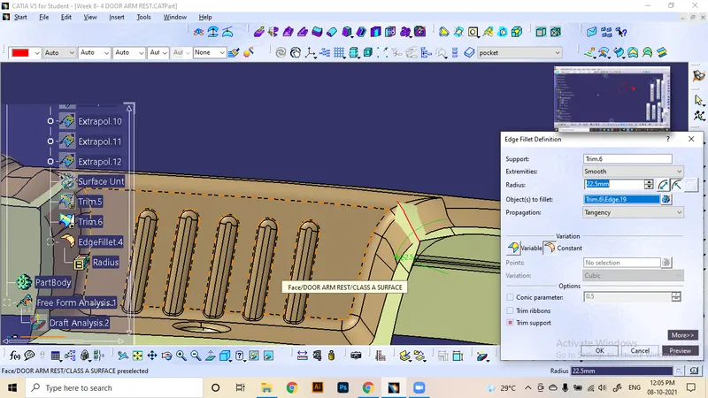
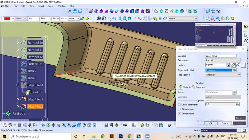
Step 3: Class C surface
- Usually, Class C surfaces are made as an extension from the edges of the class A surface.
- Sweep command is the commonly used tool to make c surfaces.
- According to the direction required by the sweeping surfaces, any subtypes of sweep can be generated as per the design.
- For the surfaces that comes parallel to the tooling axis direction, sweep must be provided along with the draft direction as tooling axis with a draft angle of 3 degrees.
- for other surfaces, the sweep can be provided with reference surfaces that comes with a +ve angle to the class A surface.
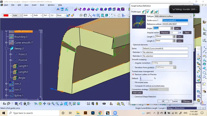
Sweep operations on the curved surfaces may lead to continuity errors and curve degeneration, in those cases, the gaps between surfaces can be filled using multisection surface. The spline must be created before it with proper tangency.
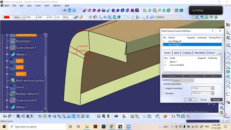
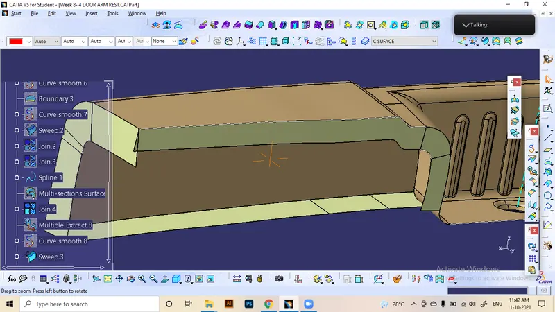
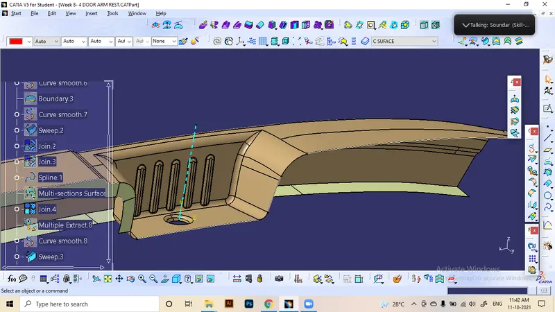
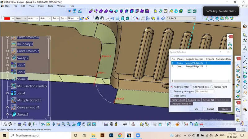
The total boundary is split into 3 individual patches. These will be intersecting at the endpoints of curvature.
So those will be extrapolated and trimmed to make the final class C surface.
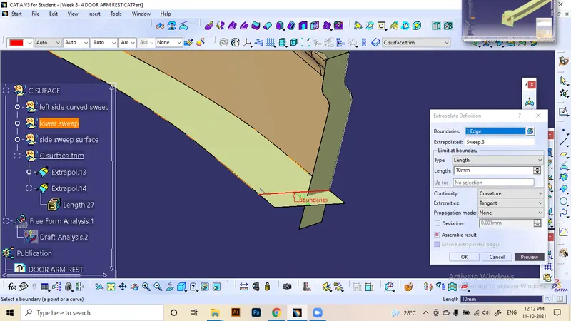
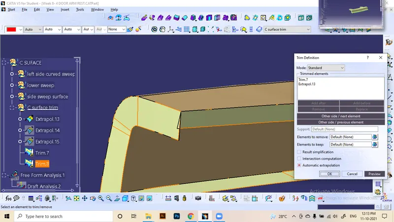
The boundary is checked for opened edges. It is fully defined.
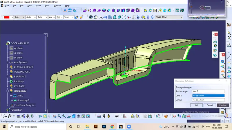
Step 4: making the final surface trim
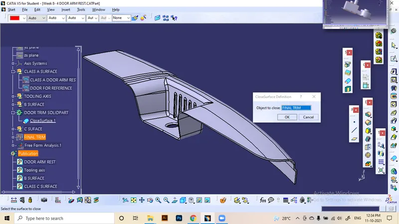
This step involves the trimming of all 3 surfaces together to make the final geometry of solidpart.
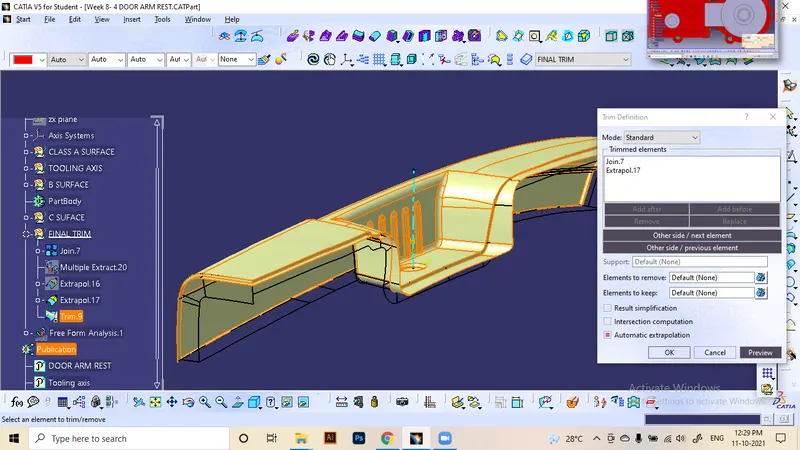
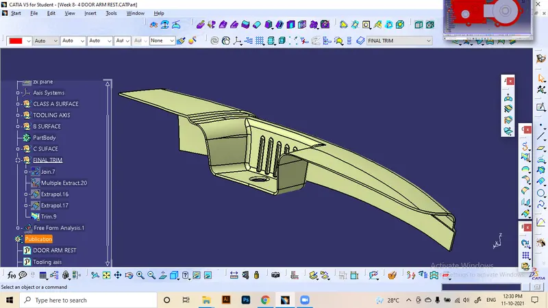
Later the surface is converted into the solid part model using closesurface tool in part design workbench.
Step 5: DRAFT ANALYSIS
Using the feature draft analysis tool, analyze the class A and C surfaces for passing the draft angle check about the tooling axis.
First, it needs to align the compass on the tooling axis, and click on the surface. Draft angle is provided as 2-3 degrees.
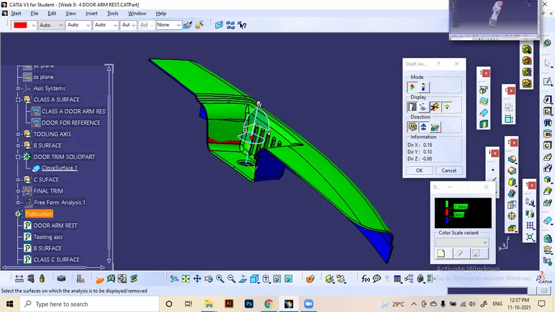
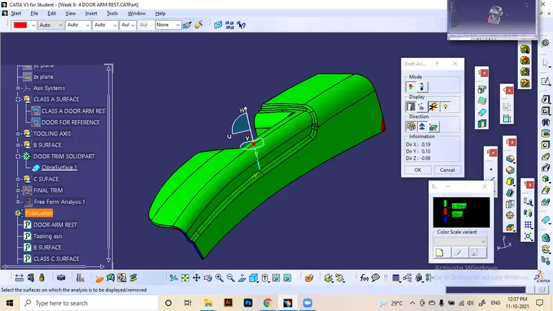
Due to the complexity of the curved surfaces and slight design deviations in the pocket regions of Class A, the draft analysis result may show the errors in draft angle.
In case, for better quality products, it already provided a side tooling axis to generate better regions by use of side cores.
Conclusion: Studied to generate Solid bodies from class A surfaces and their importance in functionality. Identified the types of errors that can be occurred during the process and the methods for re-adjusting them without major changes in forms. And to conduct Draft analysis on complex objects.