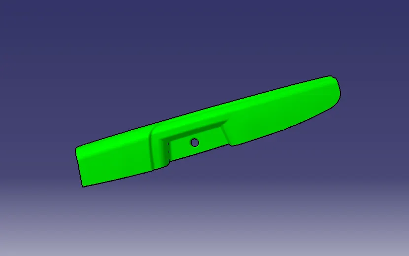
Surface Design of Door Arm Rest .
AIM:To Create a Door Arm Rest and Added thickness to it
SUMMARY:
This Project explain in brief regarding the Design life cycle followed in automotive industry by working on Practical Model Switch Bazel which is a Car interior trim Part.In this Report we have explain about the steps followed to create a solid body of the Switch bazel taking Class A Surface as Input and Creating a Tooling axis and B surface with resect to the Class A Surface and Creation of Class C Surface and also the Draft Analysis.
OVER VIEW OF DESIGN LIFE CYCLE:
- Reserach
The research design refers to the overall strategy that you choose to integrate the different components of the study in a coherent and logical way, thereby,ensuring you will effectively address the research problem; it constitutes the blueprint for the collection, measurement, and analysis of data.
- Design Requirements:
The design requirements for a product are based on the wants and needs of the intended customer. These wants and needs must be identified by the company making the product, and they are often communicated by the target customer in nontechnical and sometimes vague terms.
- Feasibility:
In some cases, a feasibility study is carried out after which schedules, resource plans and estimates for the next phase are developed.he feasibility study is an evaluation and analysis of the potential of a proposed project to support the process of decision making. It outlines and analyses alternatives or methods of achieving the desired outcome. The feasibility study helps to narrow the scope of the project to identify the best scenario. A feasibility report is generated following which Post Feasibility Review is performed.
- Concept Generation:
A concept study is often a phase of project planning that includes producing ideas and taking into account the pros and cons of implementing those ideas. This stage of a project is done to minimize the likelihood of error, manage costs, and evaluate the potential success of the intended project. In any event, once an engineering issue or problem is defined, potential solutions must be identified. These solutions can be found by using ideation the mental process by which ideas are generated.It can be done normally by Clay Modelling.
- Prelimnary/Class A Surface Design:
The preliminary design, or high-level design includes often bridges a gap between design conception and detailed design,particularly in cases where the level of conceptualization achieved during ideation is not sufficient for full evaluation. So in this task, the overall system configuration is defined, and Schematics, diagrams,and layouts of the project may provide early project configuration.During detailed design and optimization, the parameters of the part being created will change, but the preliminary design focuses on creating the general framework to build the project on.This is also Called as CLASS A SURFACE DESIGN.Styling or A class surface are the terms used in plastic product design. That mean the surface of a component which is smooth( aesthetic) or visible side to human eye after the part is assembled.
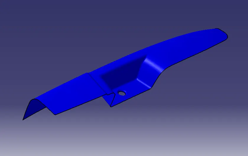
- Detailed Design:
This may consist of procurement of materials as well. This phase further elaborates each aspect of the project/product by complete description through solid modelling, drawings as well as specifications.Computer Aided Design (CAD) programs have made detailed design phase more efficient. For example, a CAD program can provide optimization to reduce volume without hindering a part's quality. It can also calculate stress and displacement using the finite element method to determine stresses throughout the part.This involves the Creation of Tooling Axs ,B Class and C Class Surface Creation with repect to the Class A Surface and also Considering the Draft angle.Design Engineer role is rominent in this stage.
Design Engineers will study the Input Class A Surface whch is developed by the prelimnary design team and the procedure folowed in creatio of the Switch bazel are as below:
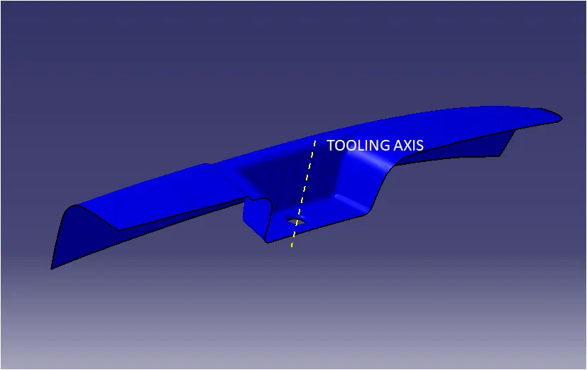
1)Tooling Axis
Tooling Aaxis is nothing but the direction in which the Core and Cavity Opens and Closes.Design Engineer works is to Analyse the Class A Surface and find out the best possible tooling direction keeping in mind all the draft angle is with respect to the tooling axis so that the Component can be easily ejected from the moulds.
2)B Class Surface Creation
Once after getting the tooling axis we need to create the B Surface which is Parallel to the Class A Surface at the distance of the thickness of the component.It also includes the Each and Every Edges,Fillets,feature which is thee in Class A Surface.In the Switch Bazel the B Surface are at the proportionate distance of 2.5mm from the Class A Surface.
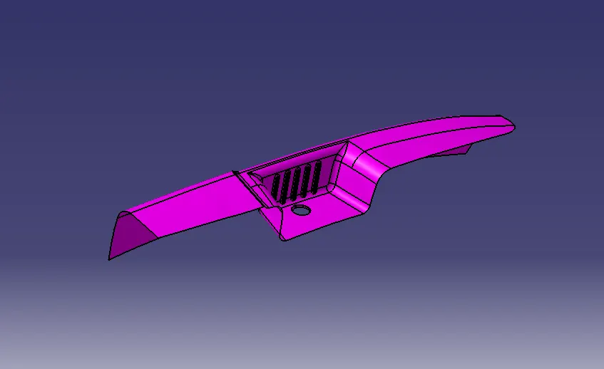
3)C Class Surface Creation
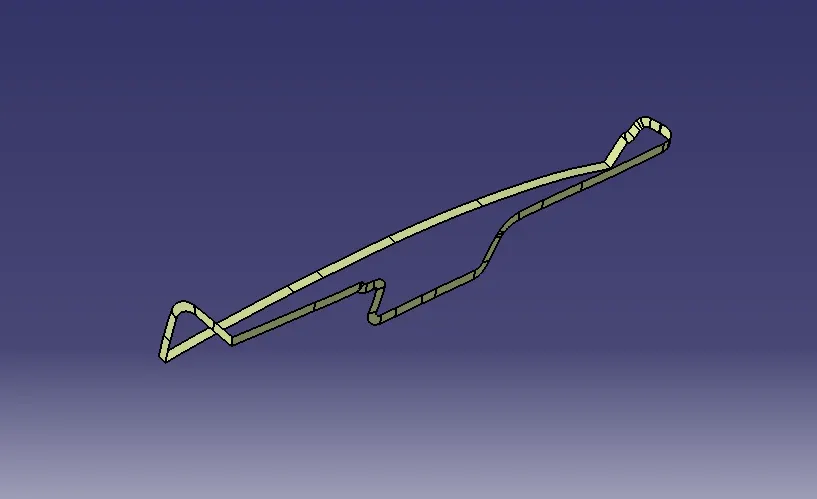
Class C Surface is Swept along the boundry of the Class A at an angle perpendicular to the CLASS A Surface with respect to the Tooling Axis Direction with a Nominal Draft angle of 3 degree.
4)Combining CLASS A,B and C Surfaces to get a Closed Surfaces
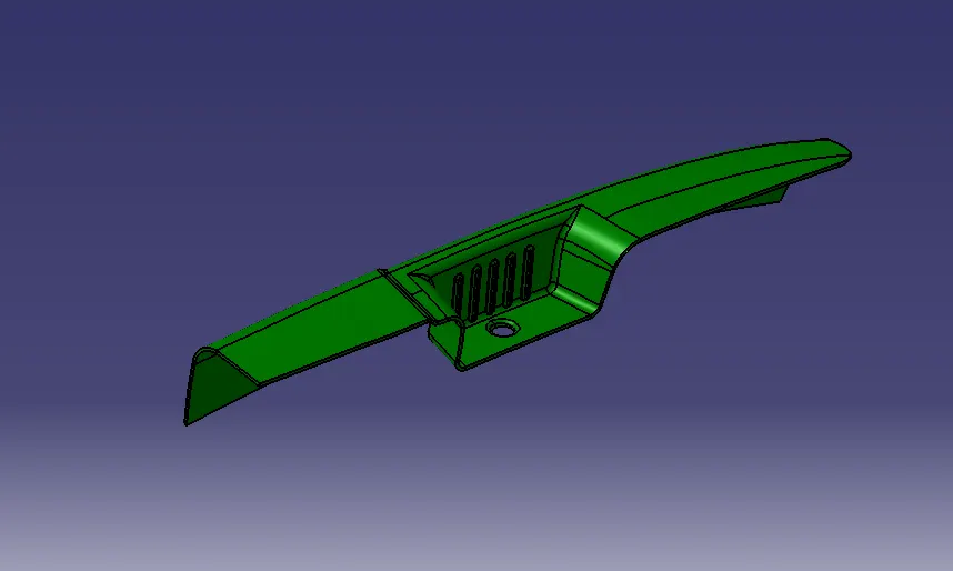
Once after Creating the Class B and Class C,First Join the Class A and Class C Surface together with a Connexity of Surface less than 0.003mm and The Surfaces are Merged.Merged Surfaces are than to be trimmed with Class b Syrfaces to get a Closed surface.
5)Draft Analysis
Parts Cannot be ejected from the tool if it is at 90 degree surface.for the reason,A small Draft angle is to be provide for each and every surface s of the Component in order to easy removal of component from the moulds without any defects.Draft is the angle in which the part is tapered to aloow it to release.Most of the part require minimum 1/2 degree to 1 degree however 3 degrees are wudely accepeted in plastic component design.Draft Analysis is the technique used to analise weather our designed product are manufacturable with required conditions or not.