Week 8 - Challenge 5 - Core & Cavity Design
OBJECTIVE: This project intends to
- Create a core and cavity for the plastic component switch bezel
- Create parting line and parting surface
Note: Draft analysis is explained in the earlier report. So now, in this report creation of core and cavity, parting line, and parting surface are explained.
INTRODUCTION:
Core and cavity are the devices in the injection molding used for molding the plastic products. In the report, the core and cavity are modeled for a plastic component switch bezel. The devices have been modeled considering the OEM standards such as the implementation of tooling axis, draft analysis, parting surface, and parting line. For this modeling CAD software, Catia V5 is used.
CORE:
- The core is a male part that forms the internal shape of the molding.
- The core is the side of the tool where the plastic material is injected from.
- The core always has a B class surface
CAVITY:
- The other half of the mold is the cavity, which is a female part that forms the external shape of the molding
- The cavity is the part where the molten material is under pressure is injected into it. The plastic part also cooled and gets solidified in the cavity.
- Cavity always has an A surface
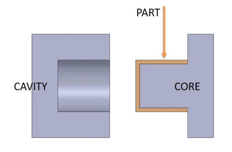
NOTE: In this core and cavity design the A surface is designed on the core and the B surface on the cavity. This is because of the instructor's guidance. (After a conversation with my support engineer Basil Sir came up with this note)
PARTING SURFACE
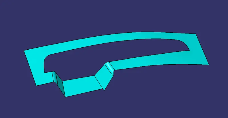
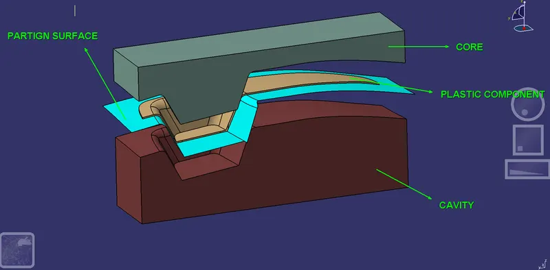
- The split face between core and cavity is called the parting surface
- Injection molding has two main components movable halve and fixed halve. During the injection molding process, these two halves are pressed tightly to seal the hollow space between them and to avoid melt flow leakage.
- When the components are pressed together the holding pressure is maintained until the mold gets opened
- The parting surface will always be on the B surface side
PARTING SURFACE CREATION
Parting surface is created by extracting the boundary of A surface
PARTING LINE
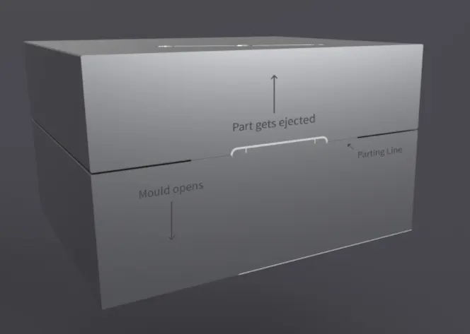
- The parting line is the area in which the parting surface and the component meets. In other words, it is the junction b/w core and cavity halves from the parting surface
- The parting line also includes side action pins, tool inserts, and shutoffs. Every part has a parting line
- Parting Lines can be split into two broad categories: Straight/Flat and Stepped/Curved.
PARTING LINE CREATION
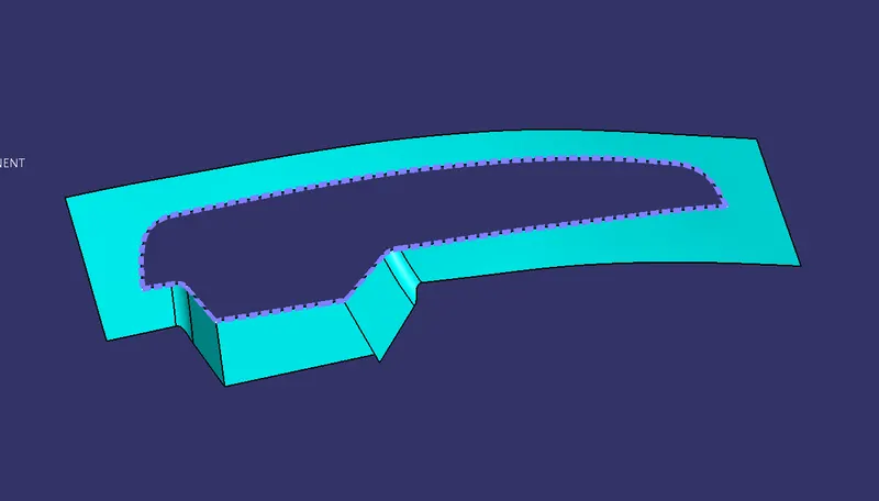
Here to create the parting line the intersection of class B is taken and joined with the class A+C surface together. The result parting line is the splitting line between core and cavity.
In the below figure the parting line is represented with a dotted blue line.
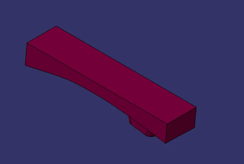
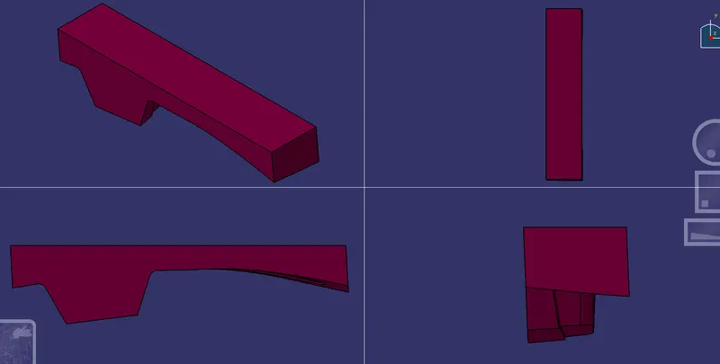
Design of Core block
The core block is designed respectively to the tooling axis. As mentioned in the earlier note, here for this model the core block holds the A surface.
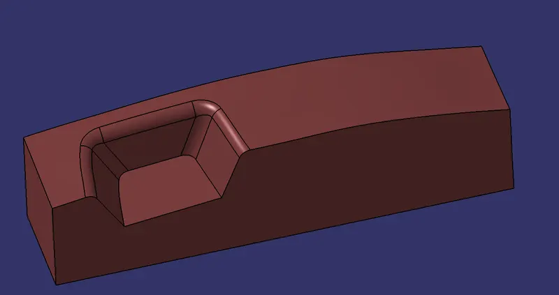
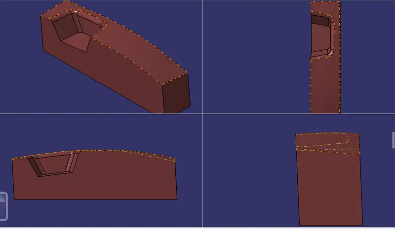
Design of Cavity block
The cavity block is designed respectively to the tooling axis. As mentioned in the earlier note, here for this model the cavity block holds the B surface.
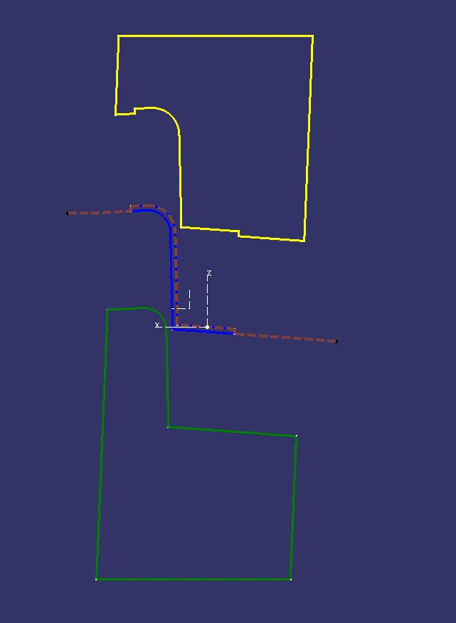
The below figure shows an intersection b/w ZX plane and Parting surface, Core, Cavity, and plastic component.
yellow represents the core
Green represents the cavity
Brown represents the parting surface
blue represents the solid body
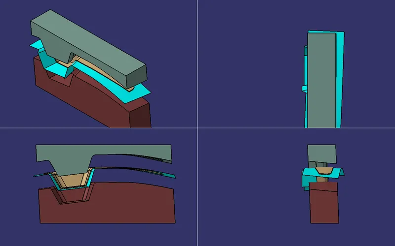
The core and cavity are translated 50 mm away from the original position.
PUBLICATIONS
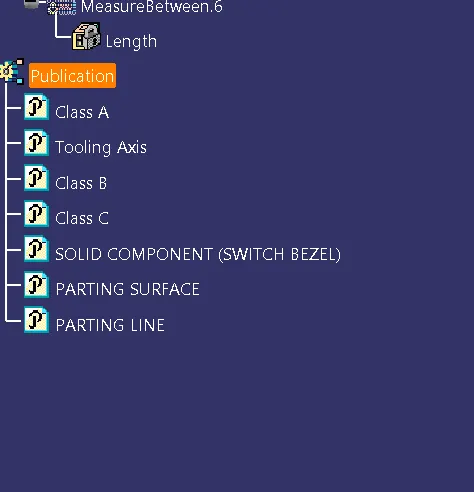
Publications are used for easy access. The things which are used very often are converted into publications here.
CONCLUSION
- In this project parting surface and parting line were created for the plastic component switch bezel
- Using surface and part design in Catia V5 core and cavity blocks were modeled
- The given project is accomplished with all the requirements