Door Arm Rest Week 8 Challenge
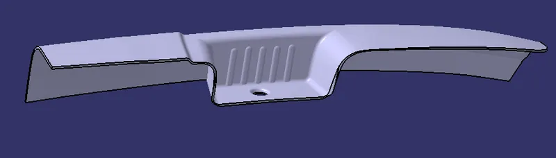
Door Arm Rest
The first step is to create the class A surface from the given surfaces by using join command. After joining check for any boundary or openings using boundary command once the class a creation is done we can publish the class a surface.
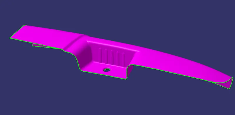
The next step is to create the tooling axis. Using the intersecting tool and intersection is created wit the surface and the XZ plane. the lines in the intersections are bisected using line command to obtain the tooling axis. But in this class a the created tooling is not able to clear the entire surface of class a as some region is hidden from the tooling axis point of view hence there arise a need for the creation of second tooling axis to cover the back wall area of the class A.
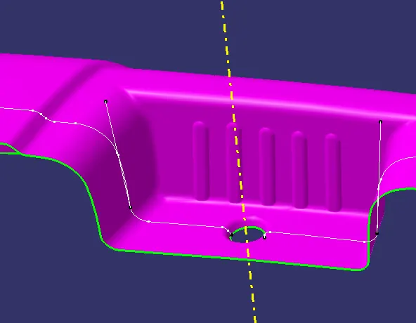
For creating the second tooling axis an intersection is made in the XY plane with the class a and a line is created with a certain angle with the intersection such that the created line is clearing the wall are of the class a, with this the second tooling axis is created.
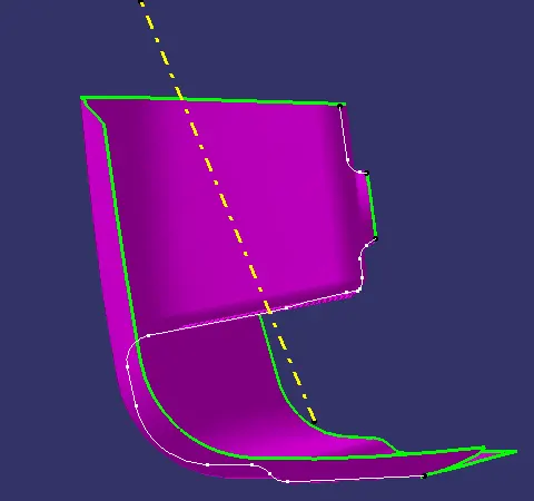
The surfaces from class a is extrapolated and offsetted to 2.5mm, the extrapolated surfaces are then untrimmed and then trimmed accordingly. After the final trim the edge fillets are provided and it is made sure that offset value of 2.5mm is reduced from the fillet value. The surface highlighted in blue is the class b surface.
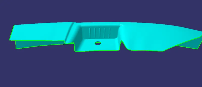
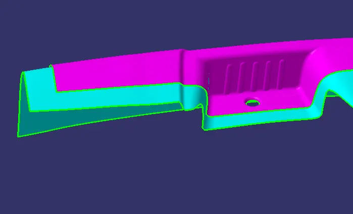
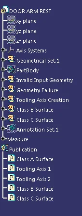
The next step is the class c surface creation. The boundary of the class a is extracted using multiple extract tool. once the boundary is obtained they are smoothen using curve smooth tool. Once the boundary is created using sweep option (with draft angle). Using the two tooling axes the surface is sweeped from the class to obtain class C Surface. The surface highlighted in brown is the class c surface. After creation of different class surfaces they are published for ease of access from the Geometrical sets.
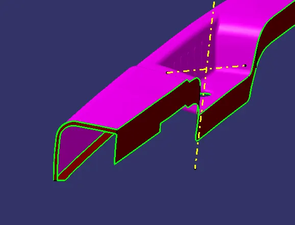
Once the 3 class surfaces are created they are trimmed with each other to obatin the final trim of the model witth the coresponding thickness.
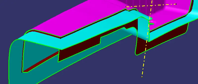
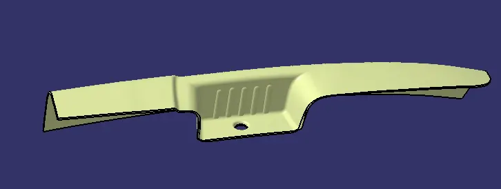
Once the Final surface trim is obtained Part Design option is selected in the start option and Close surface option is selected to create a part body with the trim surface.
Geometrical sets:
Draft Analysis:
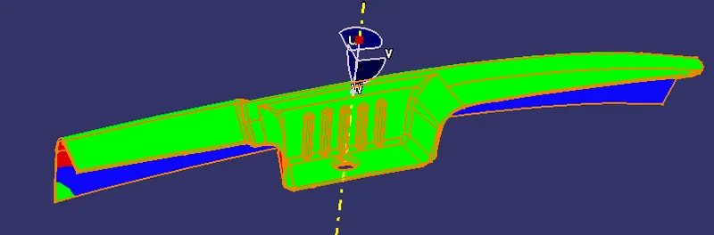
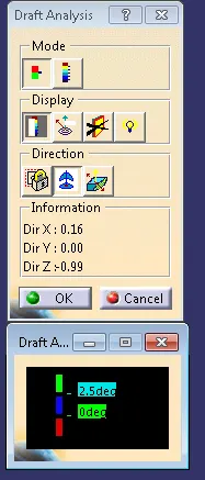
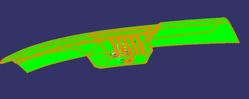
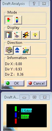
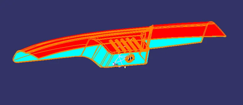
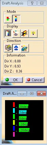
Draft Analysis is done on the Part body with respect to the first tooling axis. Using the compass option in the draft analysis window, the compass id dragged to the tooling axis and then clicked on the surface to see the draft. The colour scale shows the draft angle with respect to the tooling axis. The draft angle is provided as 2.5 deg. Full analysis mode of the body is shown in the fig below.
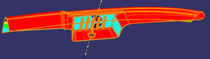
Draft Analysis is done with respect to the second tooling axis and draft angle is taken as 2.5 deg