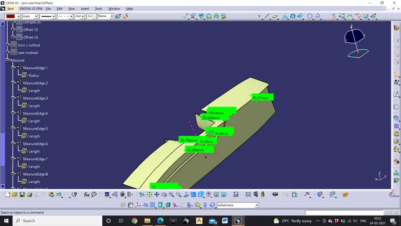
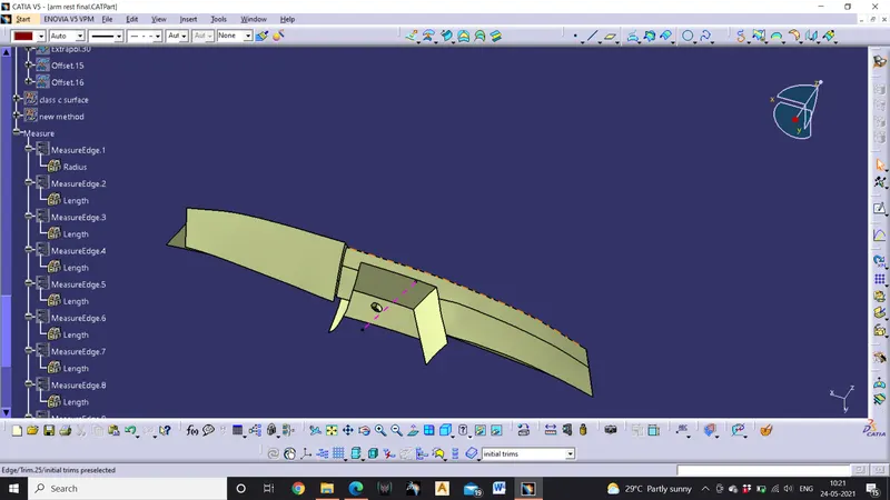
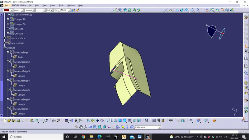
Door Arm Rest design using Catia V5
Door arm rest
AIM: to perform draft analysis and make a solid model from the given class a input of door arm rest.
Tools used:
Boundary, join, multiple extract, bisecting line, draft analysis, intersect, sweep, close body surface, extrapolate, parallel curve, multi section surface, blend, line, point
Procedure
- Creating tooling axis
- Open the given CAT part file.
- check for gaps between surfaces for that click on join and then preview
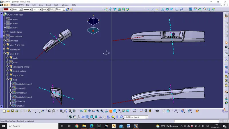
- find the correct tooling axis where the material don’t interfere with the tooling axis and all the elements can be created
- create an axis system using the surface at the bottom and use point to create the axis system
- Intersect the yz plane with respect to the class a surface walls.
- Create a line in zx plane at 6 degree with respected to intersection
- Hide the class A surface and create point to point lines on the suspected drafts
- Hence the model can’t be cleared with one tooling axis a sliding axis must be created to clear all the surfaces
- To create a sliding axis the normal line should be drawn in that direction and draft analysis should be performed and adjusting the compass position until all the surfaces are cleared
- Then lock the compass position and edit the drawn line in the direction of compass to get the main sliding axis.
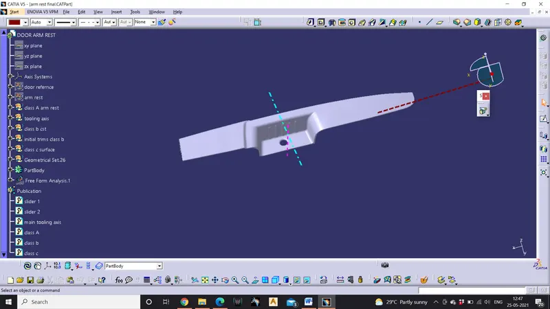
- Hence the tooling axis for the given component s created.
- Publication
- Publication is done to the component to make it visible and navigate easily
- To publish the component go to tools >publications and then select the tooling axis and the class A surface
- A separate tree structure is formed under the main part.
- Draft analysis
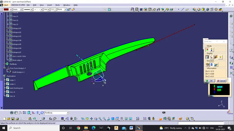
- Before going to drat analysis go to customized view parameter >under mesh >check material and then click ok
- Now for draft analyses go to insert >analysis>feature draft analysis.
- Use the compass to define the draft direction
- In the colour scale change the draft angle to 3degree.
- The component changes to green in indication of passing draft angle.
- Use running point to check the angle on the component.
- The draft analysis is complete.
- Creation of class B surface
- Extract the surfaces from the class a using multiple extract and untrim them
- Use extrapolate to make sure that all the untrims are properly intersected to trim and offset the surfaces to 2.5 mm to create the thickness.
- Trim the extra surfaces using trim command
- To create the connecting surfaces extract the boundary line and then create a sweep to get the surface and then perform the variable offset to get the simplified surface.
- Insert them into new geometrical set and name it with respective part names.
- Apply fillets to the model after creating the entire surface.
- Perform trims one at a time so that it will be clear to understand.
- Creation of class c surface
- Extract the boundary from the class a surface using boundary.
- Use sweep command >choose profile type line>subtype as with reference to surface >choose guide curve and choose reference surface >give angle as 90degree>give distance>preview.
- Use smooth curve to reduce the patches and get clean surface.
- Again perform sweep operation in the draft direction to get the desired draft angle
- Use sweep command >choose profile type line>subtype as with draft direction>choose guide curve and draft direction >give draft angle as 3 degree>preview.
- Trim class A and class c surface
- Check for boundary if any there ,then extrapolate the class A to 0.05mm ad then trim it with class C
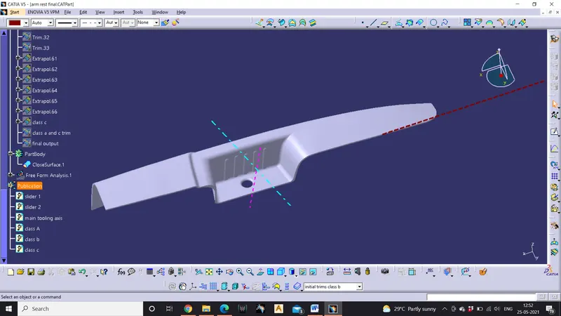
- After getting the trim then trim the class B and trim to get final output.
- Check for boundary.
- Now open part design workbench and using close body surface create a solid of the component.
- After getting close body surface conduct draft analysis some parts of the component have a draft of 2.9 degree modify the draft and for the main wall the tooling axis must be modified.