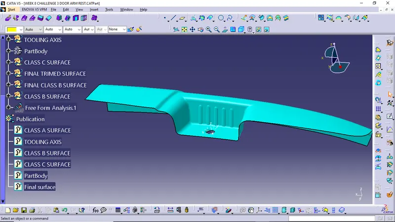
Door Arm Rest Week 8 Challenge
Aim- Creation of Door Arm rest with adding thickness and its draft analysis
Introduction-
- Class A Surface- It is outermost surface of automobile which gives aesthetic look to vehicle. It is physically touchable. It is obtained from clay modelling by reverse engineering. This surface is given input to plastic product designer to work.
- Class B Surface- This surface is created by taking offset from class A surface. It is the surface on which all engineering features like screw bosses, dog house, rib and mounting are created.
- Class C Surface- This surface which joins the class A and class B surface together.
- Tooling axis- It is the direction in which core and cavity open and closes.
Procedure-
- Checking continuity of class, A surface.
- Deciding feasible tooling direction and creating tooling axis.
- Performing draft analysis on class A surface.
- Creating class B surface from given class A surface.
- Creating class C surface to join A and B surface.
- Creating solid features by using closed surface features.
- Performing draft analysis on final plastic component.
Checking continuity of class A surface.
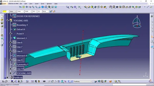
We have to check continuity of given class A surface to ensure class A surface is properly joined or no discontinuity present. This can be done by using boundary features.
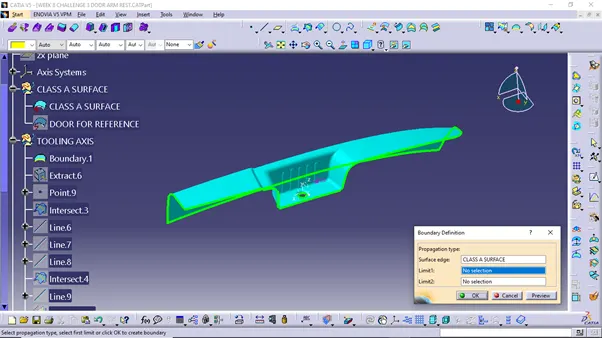
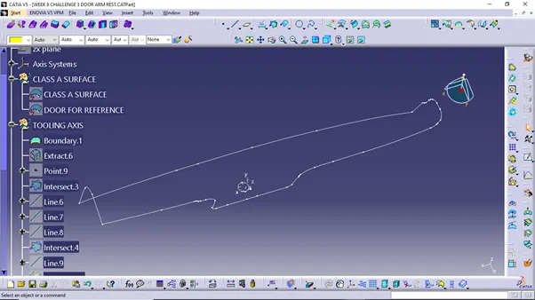
Extracting the boundary of given class A surface we also check that continuity visually.
Creating tooling axis
Tooling axis is the direction in which core and cavity or mould opens and closes. A small draft angle is provided to each and every area of the component in order to get an easy removal of the component from the tool. Draft analysis technique is used to analyse whether our part model created in cad is manufacturable based on the draft condition applied.
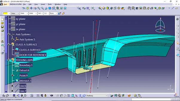
So first we have to create main tooling axis for all surface except for side core surface or pocket.
Performing draft analysis on Class A Surface
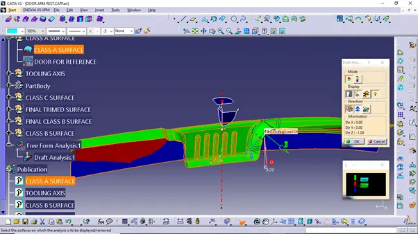
- To perform draft analysis. Go to insert-Analysis-Feature draft analysis.
- Switch customize view parameter mode to
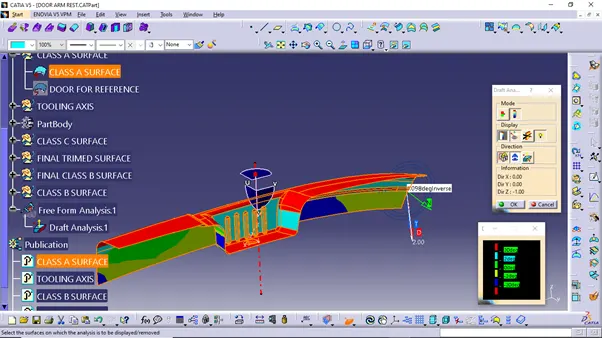
- Click on compass icon and align it with the tooling axis and click on the surface. we will get our result.
- From the below image it is seen that surface in green has more than 3-degree draft is most required for tooling feasibility.
Creation of class B surface from given class A surface
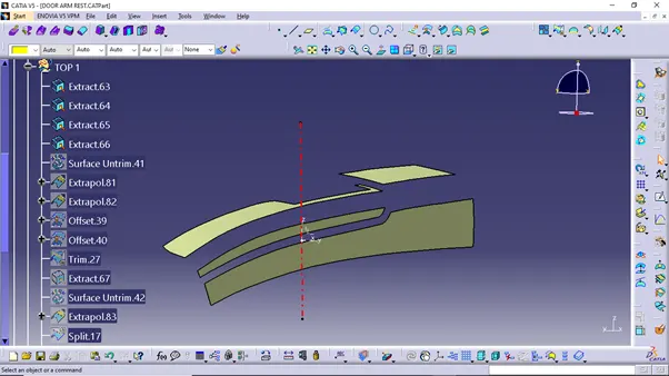
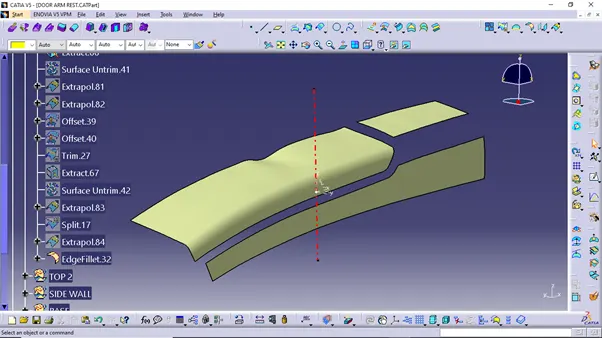
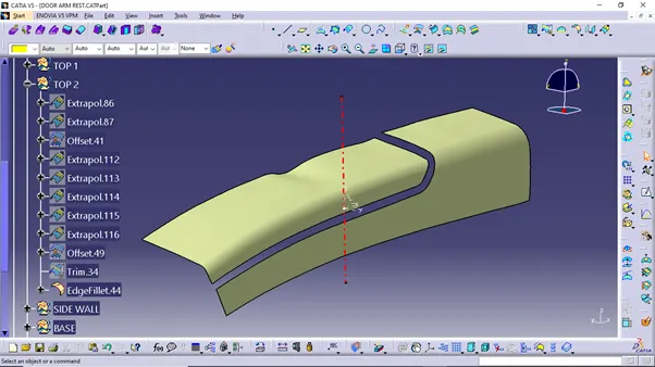
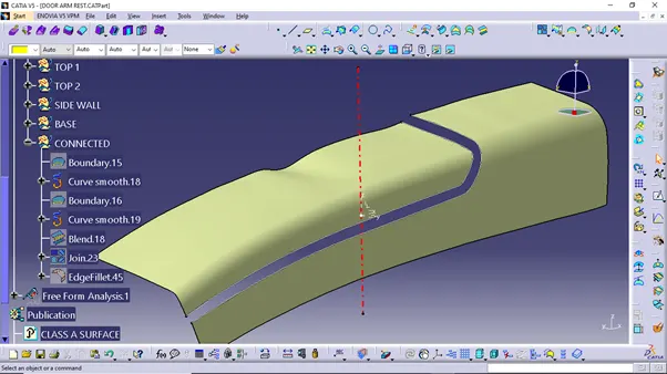
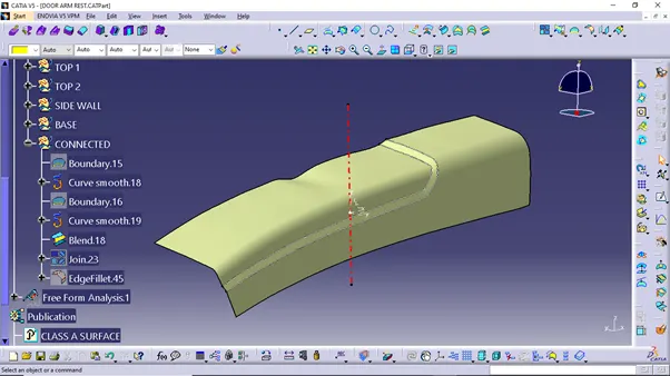
Divide class A surface in to surfaces namely Top 1, Top 2, Side wall, Connecting surface, and Base. Work on each surface separately to obtained class B surface.
Follow the same procedure for all surfaces except for connecting fillet surface.
- Extract the class A surface
- Un-trim the surface
- Extrapolate untrimmed surface
- Offset it by 2.5 mm distance.
- Trim unwanted extra surface
- Applying fillet as per formula to obtained uniform wall thickness.

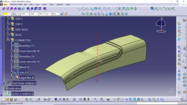
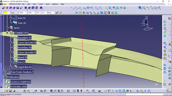
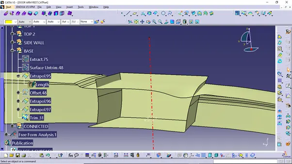
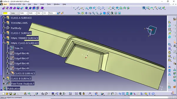
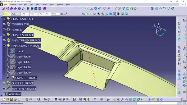
Creation of class C surface to join A and B class surface.
To obtained C class surface followed below method .Entire C class is created in steps.
First sweep extracted curve at 90 degree to reference surface as in figure below.
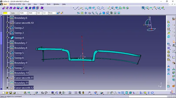
Sweep curve in draft direction and created surface. Three patches of surfaces created.
Now extrapolated sweep surfaces then split by line and formed multi-section surface.
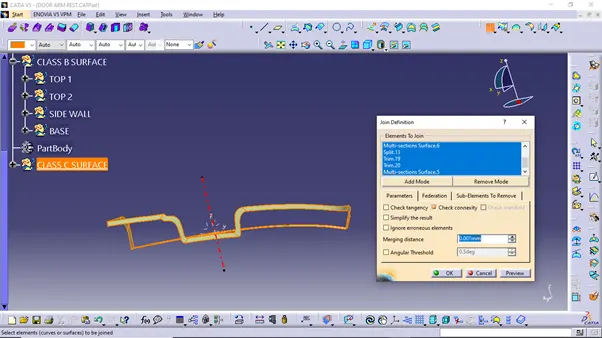
Join class A and C surface together.
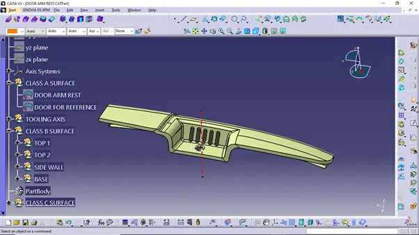
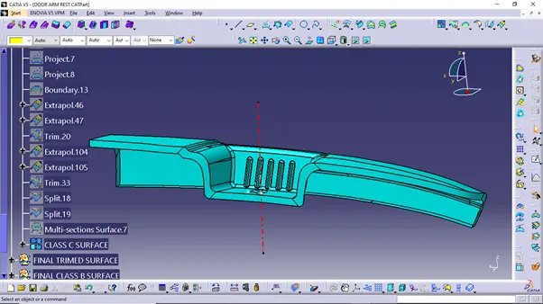
Trim this joined surface with class B surface result in closed surface.
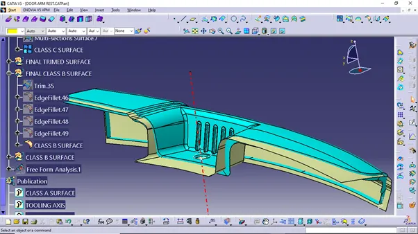
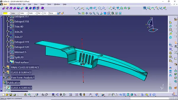
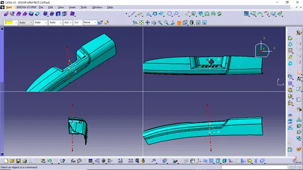
Creating solid feature by using closed surface
Solid model is created from closed surface in the part workbench by using close surface command.
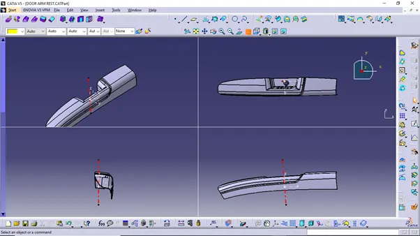
Performing draft analysis on final plastic component.
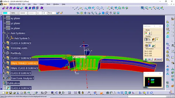
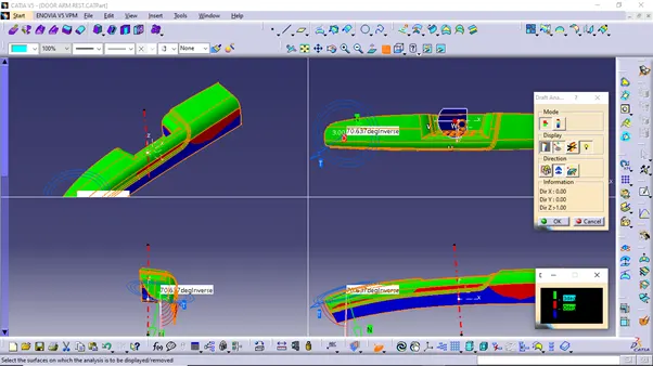
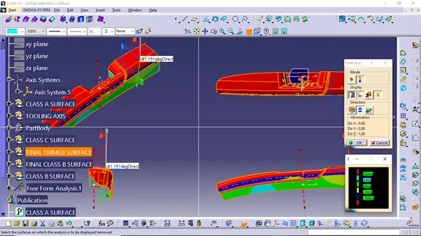
Image of the expanded tree structure for the geometrical sets and part body.
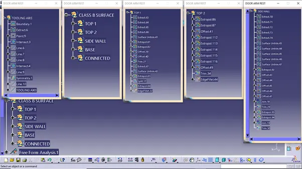
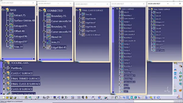
Image of the publication of tooling axis and class A,B and C surface.