DEVOLOPMENT OF A DOORTRIM PANEL
Aim : To create a CAD model of a side door trim panel from given class A surface .
Objective:
a) Creation of side door trim panle from given class A surface . Apply thickness to it and use attachment features .
b) Creation of flanges and heat stakes from given master sections .
c) Creation of dog house and various attachment features using industry standards
d) Performing draft analysis and ensuring the features and surfaces clear it .
INTRODUCTION-
The door panel is the interference between the interior of the car and the inner workings of the door. Generally, the door panel is divided into two parts of easy designing like arm rest, map pocket, lower substrate, bottle holder, these requires one of the toughest requirements among the interior parts of the car. This should be designed to with stand the load while being less than 2mm in the thickness and also protect the occupants during collisions. Door currently has an inner full width panel consisting of electronic windows. Central locking system and speakers. These panels typically consist of a covered with either textiles or plastics.
TOOLING AXIS
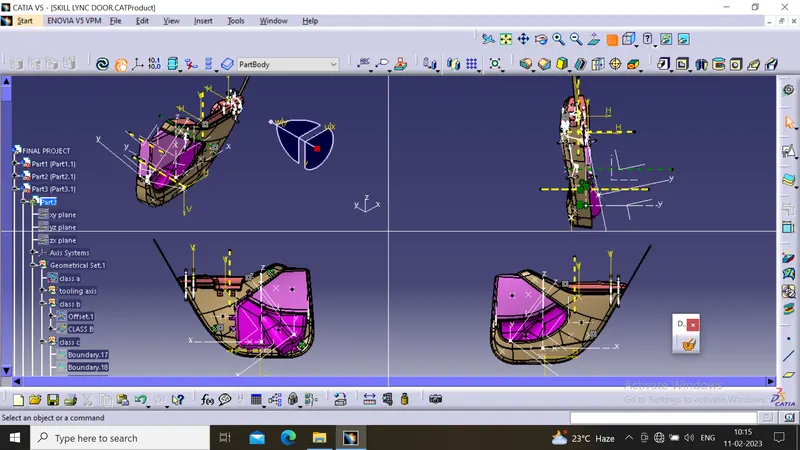
Tooling axis is the axis along which the core and cavity opens and closes. It is very important to define the tooling axis in the first step while designing a component as it is the main component which helps us to run draft analysis on class-A at initial stage to see if we can move ahead. Also for later stage, tooling axis is the direction along which class-C surface and the draft to the components is given.IN this model we have a tooling axis in the perpendicular direction to the entire door trim that is y-direction in the model. It is very evident that switch bezel will require a side core, so another tooling direction is made specifically for switch bezel. Apart from these two tooling axes we also have a side core tooling axis for dog house.
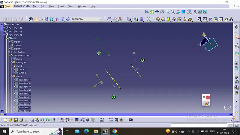
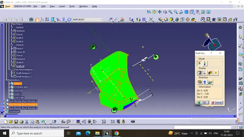
Procedure to check for Draft analysis
1)Once the tooling axis is created , publish it and the component using Publication from tool option .
2)Insert Feature draft analysis option from insert tool bar
3) Change the view option to customize view parameters and click on material option under shading .
4) Now click on the axis option from Draft analysis tools , allign it with tooling axis and click on lock option to lock it .
5) Change draft angle value to 3 degree . Click on quick analysis mode to display feature according to given color scale . Check from all views to ensure the draft analysis is cleared .
6) Since the created tooling axis does not clear the draft analysis at the created axis , click on the lock axis button to unlock it . Now rotate the tooling axis by left clicking on the top round portion of the axis system . Rotate the axis till maximum clearance is obtained . Now right click on the axis and click lock current axis .
7) Create a line using the initial axis origin and this axis using point and direction (using compass direction) option . This is our required tooling axis .
8) Now if we check for draft analysis, we can observe that the ribbed area has not yet cleared draft analyisis. Hence we need to create a side core tooling axis . To do this , create a line using point and direction option with Y direction .
9) Repeat steps 1 to 5 to ensure the remaing portion which was not cleared using Tooling axis has been cleared using this axis .
DRAFT ANALYSIS FOR A SURFACE :-
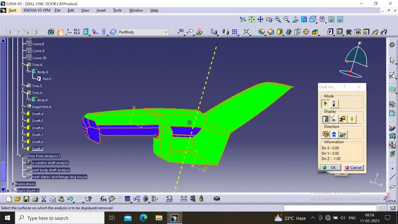
1.DOOR ARM REST
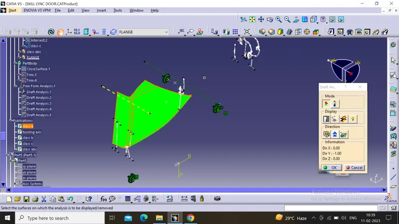
2.MAP POCKET
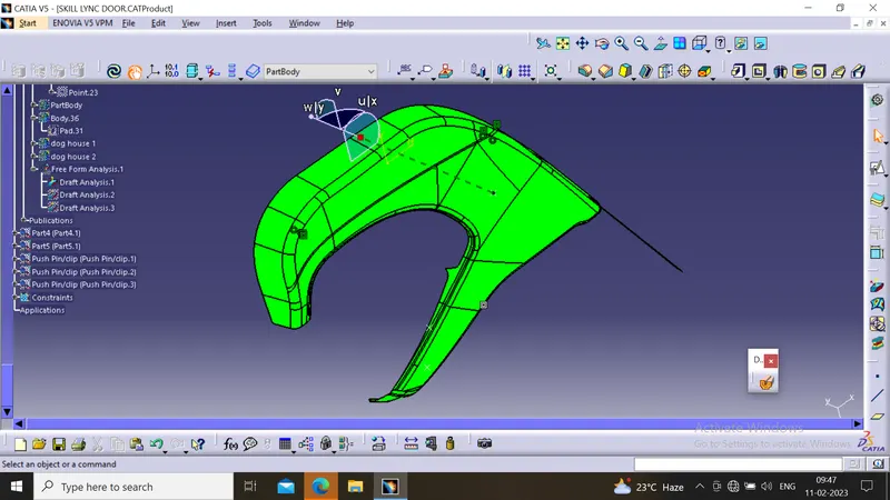
3.LOWER SUBSTRATE
4.BOTTLE HOLDER
A surface:
A surface is the styling surface that is visible to the consumer and gives an aesthetic look for the model designed. Surfaces which are having curvature continuity is also called Class A Surface. Engineering features are not added to this surface. Class A is any of set freedom surface high efficiency and quality. Although strictly it is nothing more than surface have curvature and tangency alignment.
THESE SURFACES ARE GIVEN BY QUESTION ITSELF.....
B Surface:
Class B surfaces are the secondary surfaces that you can see sometimes includes all the engineering features such as dog house, locators, ribs, flanges, etc. This
surface is the direct offset of the Class A surface which gives thickness to the component.
| CREATING B SURFACE |
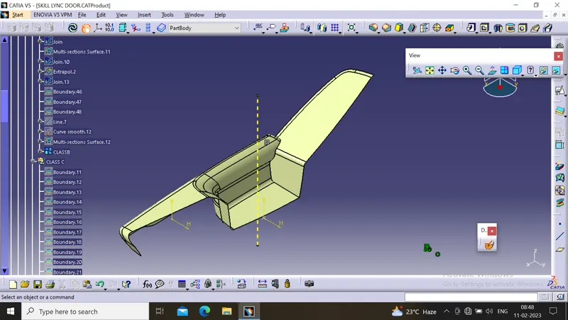
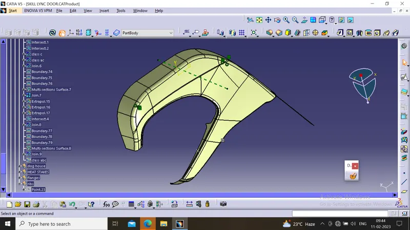
Class B surfaces are the secondary surfaces that you may see sometimes or may not, but are less important. These must be smooth and "error-free" as well, but are not held to the standards that class A surfaces are. After creating the Tooling axis, B surface is to be created which is nothing but the surface parellel to the A surface. B surface contain all the fillets and the edges which the A surface containsDepending on the geometry, the extraction and offset of the fillets might generate non-uniform thickness. So it is advisable to extract only the flat surfaces and then apply fillets at the end of Class B formation.
lets start the process of creating class B by choosing the respective A surface and extract with no propagation option then untrim the extracted surface to get the basic geometry.after getting the original/basic surface the surfaces have to overlap each other in order to facilitate trimming therefore extrapolate it up to the required dimension.then we finally trim them.
now after trim operation is done offset the Trimmed geometry by the value of the thickness of the component,this Offset is our B Surface.at last We will measure the filler radius values to create fillets on the class B
This can be done by offseting the class-A surface and by reparing the patches that are forrmed while offsetting the class-A surface.
- First offset the class-A surface
- We can observe it has created patches at two stages.
- So we have to repair them by using multi section surface command.
- Name the developed repaired surface ass Class-B Surface and make it publish.
1.DOOR ARM REST
2.LOWER SUBSTRATE
3.MAP POCKET
4.BOTTLE HOLDER
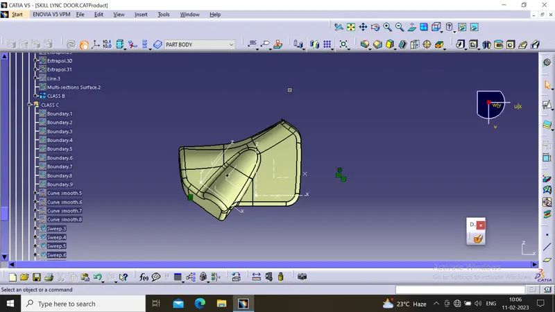
]C Surface:
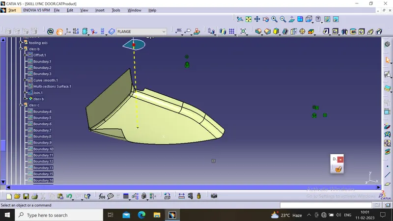
This surface is the combination of the Class A and Class B surfaces also they are the backside surfaces that can have tool marks, flash, and other imperfections without hurting appearance, function, etc.
C surface is created by extracting the boundary of A surface and using the sweep command.
COMMANDS USED:
1.EXTRACT AND MULTIPLE EXTRACT.
2.BOUNDARY
3.SWEEP
4.SPLIT
5.BLEND
6.MULTI SECTION
7.TRIM
8.JOIN
C surface is the part of the geometry that connects Class A with B surface.Rules to be followed for C surface creation is A minimum draft of 3 degrees should be provided to facilitate the Ejection of the Molded component.The parting line should be on the B surface. This means that the draft should sweep outwards, from the C surface
1. DOOR ARM REST
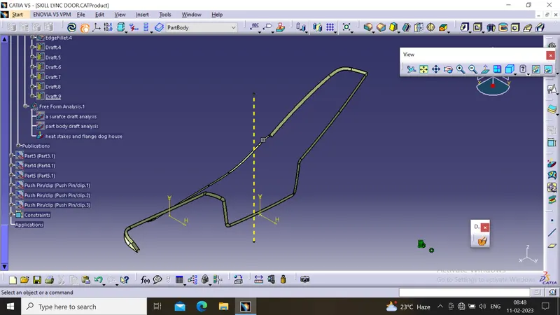
2.LOWER SUBSTRATE
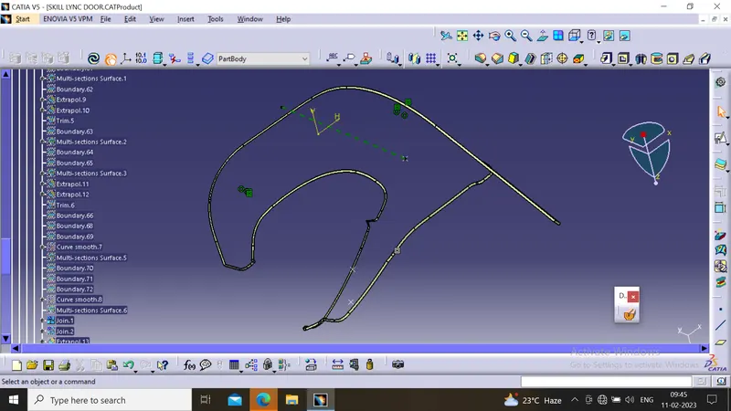
3.MAP POCKET
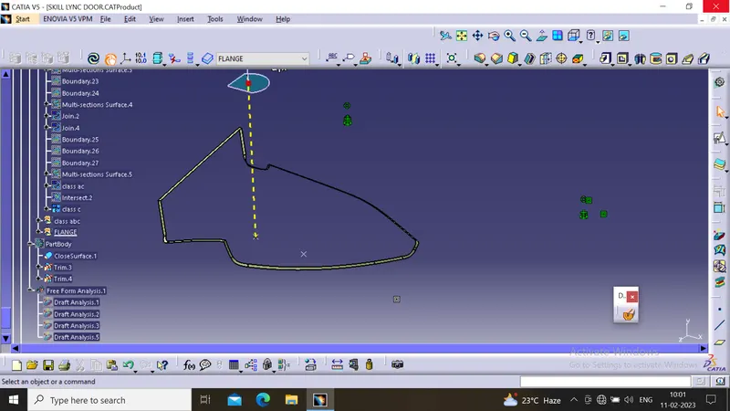
4.BOTTLE HOLDER
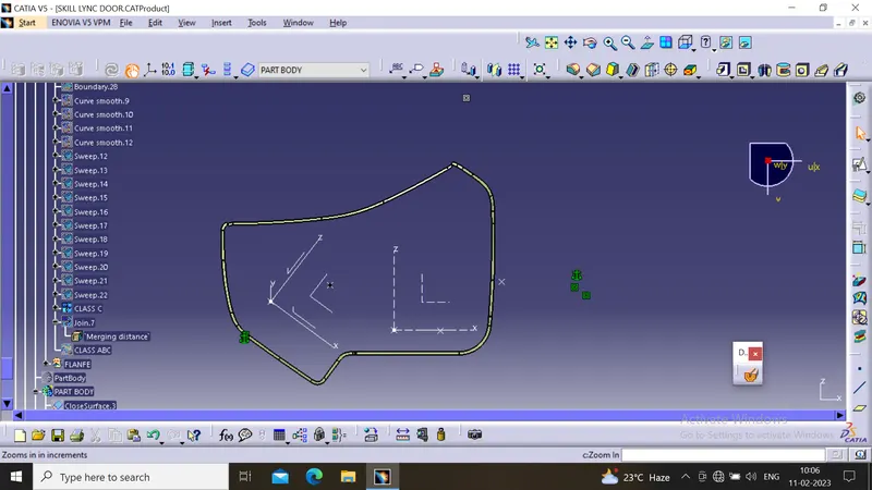
ENGINEERING FEATURES
[FLANGES,HEATSTAKES,RIBS,DOG HOUSES]
1.DOOR ARM REST FLANGES AND HEAT STAKES
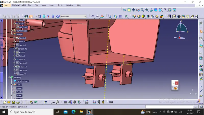
2.HEAT STAKES ,DOGHOUSE,RIBS
SCREW BOSSES
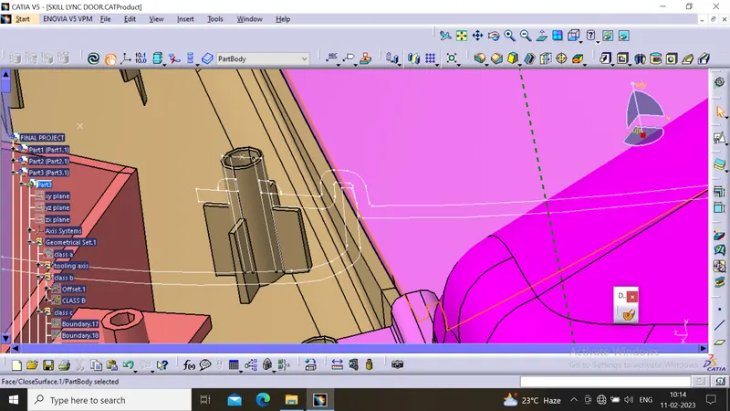
The boss is one of the basic design elements of plastic molding, bosses are usually cylindrical because that is the easiest form for the machine in the mold and it is also the strongest shape to have in the molded part. the boss is used whenever we used a mounting point, a location point, or a reinforcement around holes. the boss may receive an insert, a screw, or a plain either as a slider or a press fit.
In other words, the boss is not as simple as it looks depending on its use, it may have to stand up to a whole combination of force- tension. compression, torsion, flexing, shear and bursting so it must be designed accordingly.
HEAT STAKE
The use of heat stakes is to attach two plastic components permanently, a total of 11 heat stakes were placed at different locations on the lower substrate .one heat has been created into armrest parts which will be attached to the upper substrate. Following the master section, the outer diameter of the heat stake is 7mm and the inner dia is 5mm, necessary slots are made onto other parts where the heat skate will attach together, and a draft of 0.5deg has been given to all the heat stake
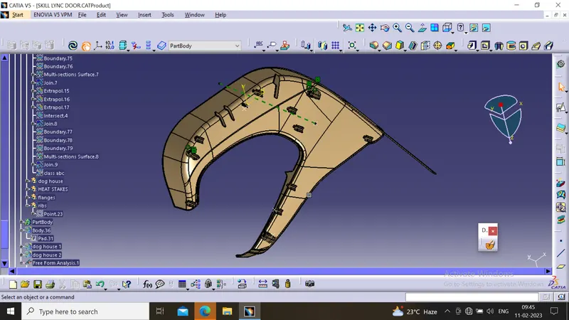
3.FLANGES
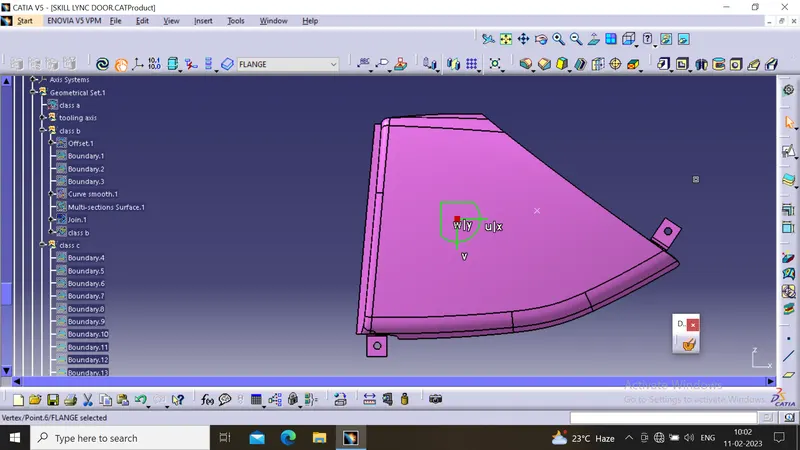
4. FLANGES FOR BOTTLE HOLDER
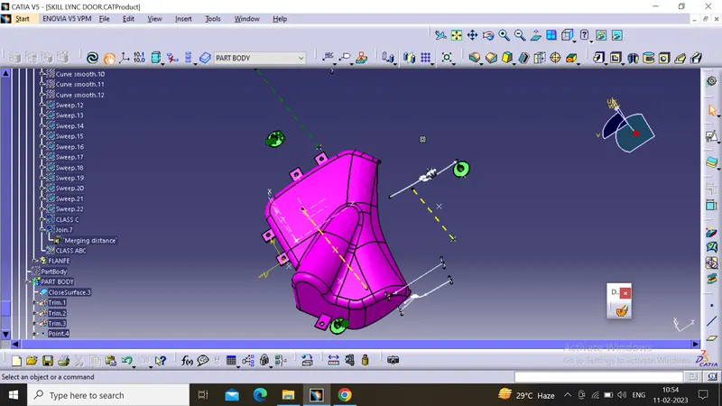
DOG HOUSE WITH PUSH PIN
(1) DOG HOUSE :
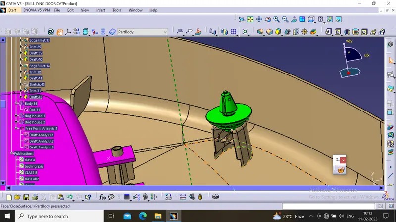
Dog house is an engineering feature used in plastic trim design. Dog houses are used as supporting feature. Sometimes other engineering features like snaps; locators etc. are mounded on them to increase their strength.
Dog houses are subjected to draft analysis to prevent breakage of the component during ejection from mould cavity. Dog house and other engineering components are built on B-surface.now we will proceed with creating a dog house and mount the boss on it by following the design rules mentioned below :
Doghouse design guidelines (used as reference) : 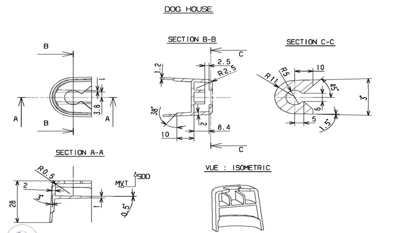
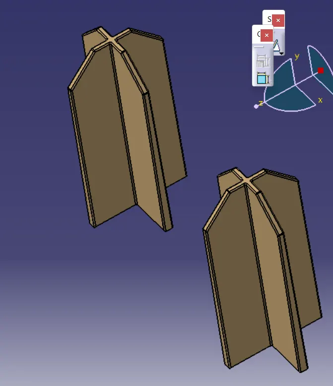
REACTORS
DRAFT ANALYSIS FOR TOTAL PART BODY(A,B,C) SURFACES
| FINAL DRAFT ANALYSIS |
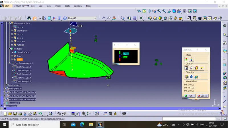
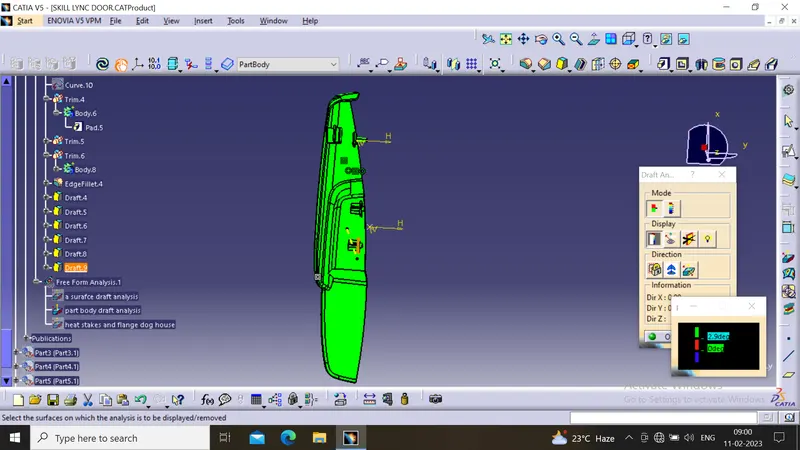
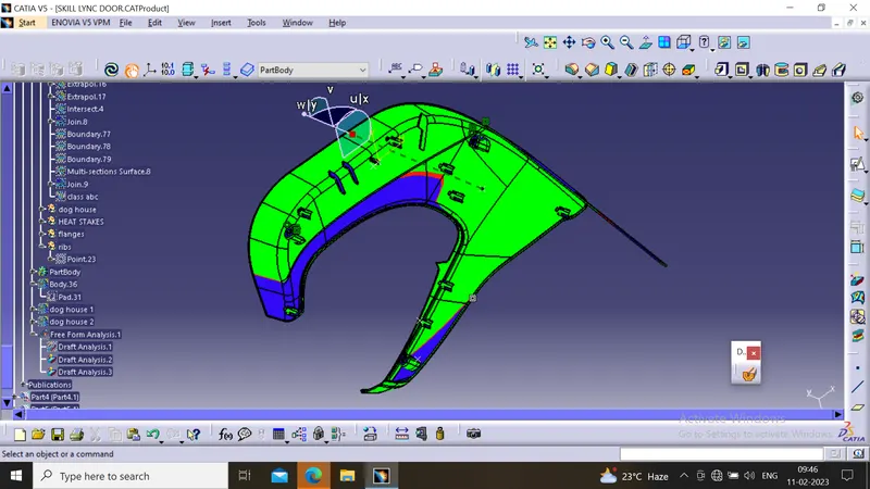
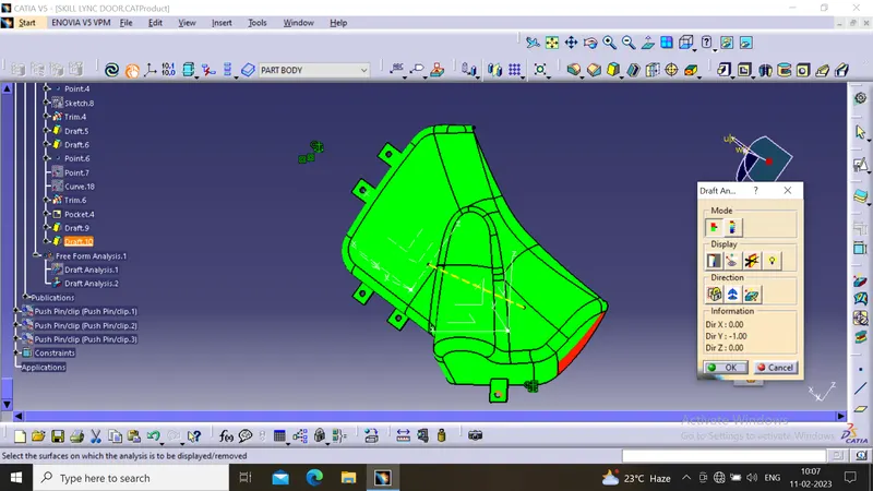
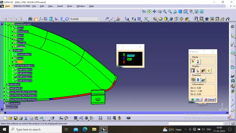
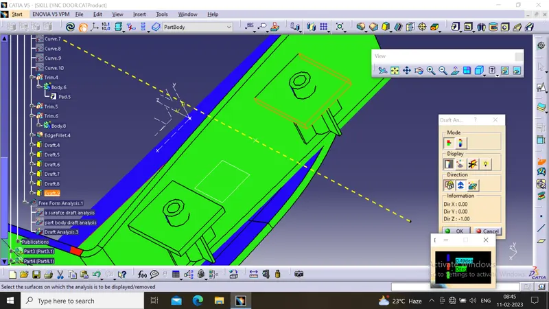
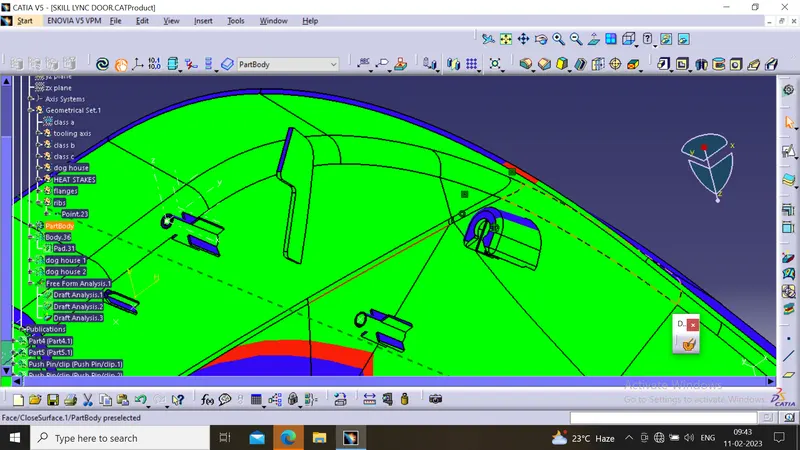
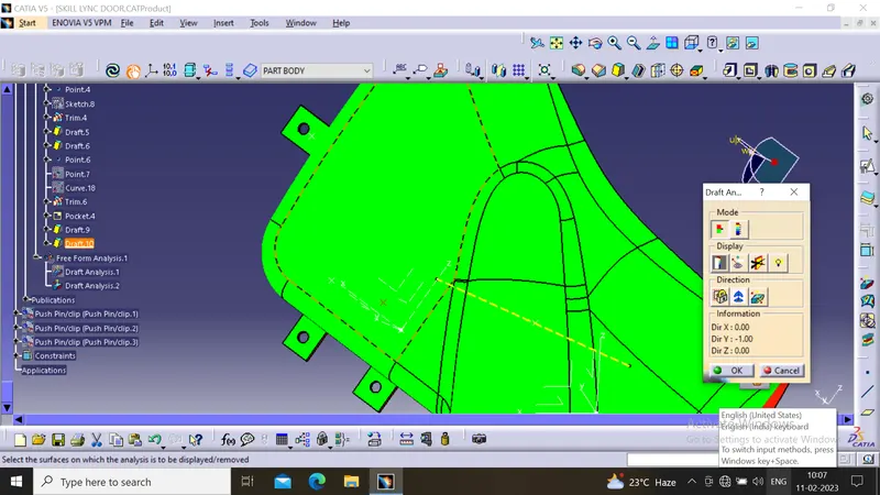
In the injection molding process, plastic products are difficult to demold due to friction force between the cavity and products, thus, finished products might be deformed or damaged. Therefore, designers should add a draft angle to the geometric surface of products, which is parallel to the unloading direction, in order to help the products eject smoothly from the cavity. This study uses CAD software as the main architecture to develop the function of automatic draft angle recognition and construction. The study is divided into three stages. First, the geometric features of products are identified in the CAD model by induced algorithm, then the quilts to be added in the draft design are determined and classified. Finally, draft angles are created in different ways according to different surfaces
The draft analysis button within CATIA V5 will help you quickly gather the draft angle on multiple surfaces without the need for tedious manual measurements.we go to Insert > Analysis > Feature Draft Analysis.it will automatically enables a popup window to ensure you have the Material view mode ON.
once the material mode is selected Define the Draft direction using the "Compass" option then drag the Axis system representation close to the model and align it along the tooling axis to avoid the accidental movement of compass we will lock the Draft direction using lock compass option in the menu when we right click on the compass,set the Colour scale as shown below
1.MAP POCKET
2.DOOR ARM REST
3.LOWER SUBSTRATE
4.BOTTLE HOLDER
DRAFT ANALYSIS FOR ENGINEERING FEATURES
PART BODIES
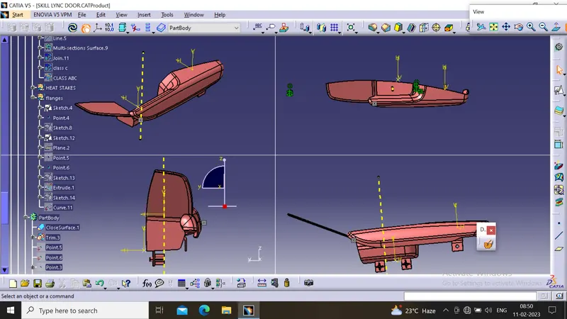
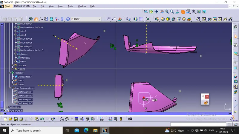
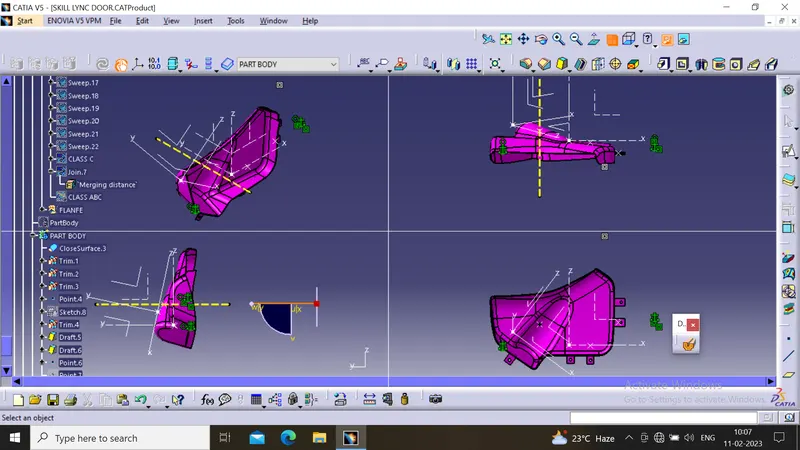
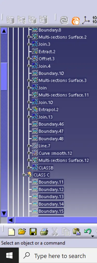
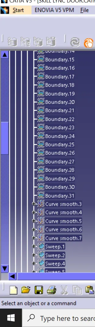
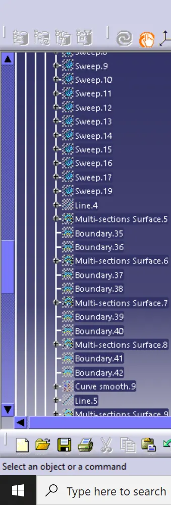
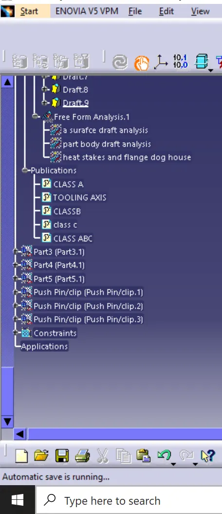
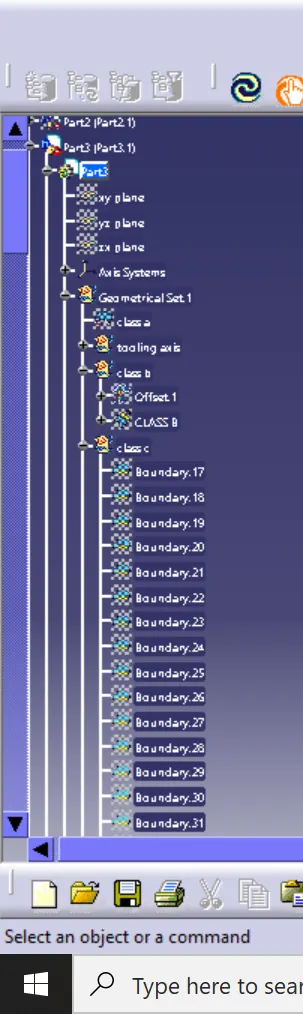
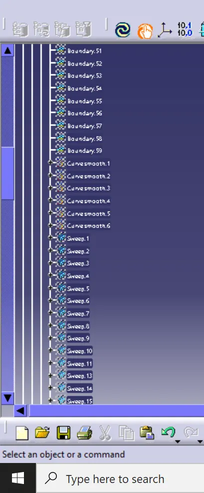
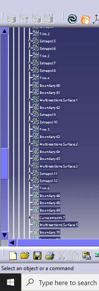
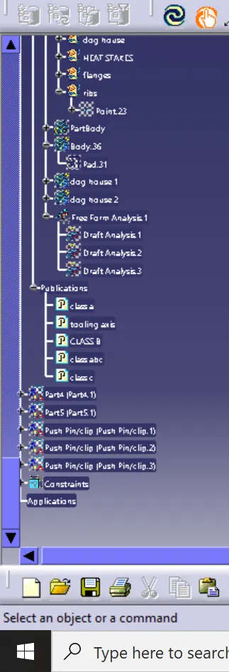
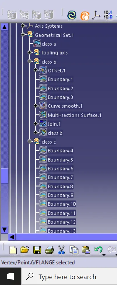
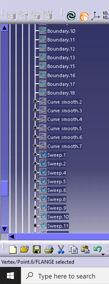
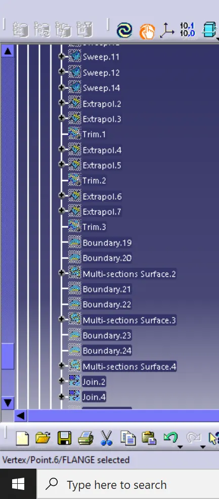
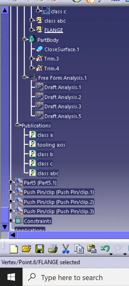
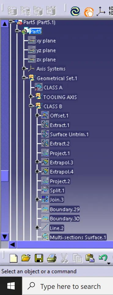
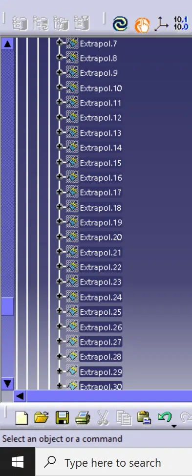
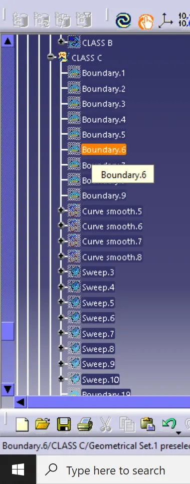
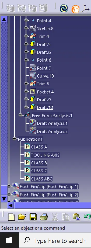
TREE STRUCTURES
1.DOOR ARM REST
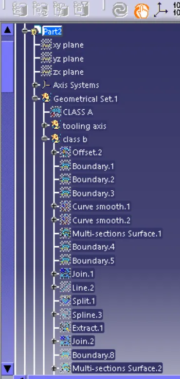
2.LOWER SUBSTRATE
3.MAP POCKET
4.BOTTLE HOLDER
SCREW BOSSES ARE CREATED USING MASTER SECTION
FINAL PRODUCT
CONCLUSION
The door panel successfully designed by following all design rules used in automotive industry. All the attachment feature are properly placed at different location.